If you’ve not been paying attention to the manoeuvres around Vero Software, it’s perhaps a good time for quick recap.

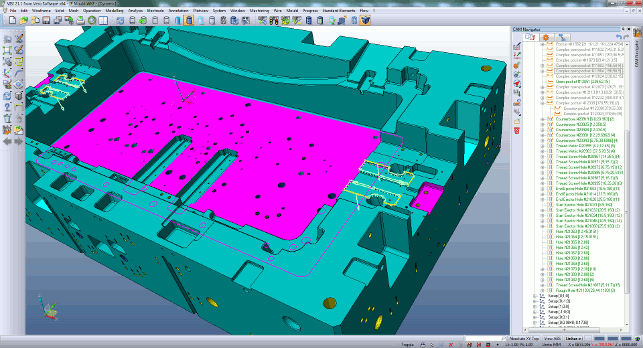
VISI 21 brings improved Automatic Feature Recognition (AFR) for complex plate geometry
The company has recently been acquired by Hexagon Metrology, but preceding that the company had been expanding its portfolio of software tools through pretty aggressive acquisition.
Under the Hexagon banner now, we have VISI for mould and die design, Surfcam, Edgecam, PEPS, WorkNC, Alphacam and not to forget, Radan for sheet metal design and fabrication.
While it’s still early days in terms of discovering what Hexagon plans to do with this wealth of manufacturing related technology, it is clear that the company is looking to bring these tools together, find where the best practices lie in each, and roll them out across many of those products — all of which is evidenced in this latest VISI 21 release.
User experience
User experience is, of course, all about the complete process, rather than just the user interface.
So, with that in mind, it’s nice to see Vero integrate previews of native part files in the Windows environment. Instead of the familiar static thumbnail in Explorer, you now get a dynamic preview of the part that’s rotatable and zoomable, making life much easier before you’ve even fired up the software.
VISI has been going through redevelopment and refreshing of the user interface for some time and it’s now looking pretty clean and clear. This release, however, takes a step back, evaluating the best practice across all of the company’s products and adapts the user experience to give the best experience, rather than purely relying on how things have been done historically.
Selection of geometry is a good example. You now have much more flexibility, particularly when selecting multiple faces or other geometry types. A window (or polyline) select will, as the default, select everything inside that box, whether it’s visible or not.
You also have options to select just the visible entities or faces that have just edges visible (the latter is particularly useful for selecting holes and pockets when you’re looking directly down onto them).
It might sound like a small update, but when you consider the complexity (in terms of numbers of surfaces) involved in mould and die design, it’ll prove useful.
Moving onto the modelling and mould design tools, there’s been a lot of work across the board. Much of this revolves around the design of complex moulds and die, in particular, where you’ve got multiple cavities in a single mould as well as more complex mechanisms.
Multi-cavity support (in this release, this pertains to instances of the same part) now gives you a mirroring tool. This creates a component copy and allows you to array them as you need. The system maintains the link to the original core/cavity geometry, but allows you to edit any of those instances and have the rest update automatically.
VISI 21 also includes many new surface modelling tools which expand on the previous toolset for surface extension, surface tangency, and blending between curves and faces with curvature constraints. The new tools are particularly important for mould tool parting faces and sheet-metal forming stage development.
Mechanism design & test
VISI 20 introduced mechanisms to the existing constraints tools for linking together components, but these were manually controlled (you had to drag and drop them to move them).
VISI 21 introduces more formalised constraints that closer mimic real world mechanisms such as springs, trajectories and paths, gears, racks and pinions. This means you can not only do the complex work of developing the moving components of a mould,
but also simulate their action to ensure that they’ll work.
Also related to this are animation tools that allow you to define a timeline for those animations, and they work in three modes.
Normal lets you just move components. Collision detection will stop the parts (and highlight those affected) when there’s a collision (useful for finding and fixing mechanism lock).
Physical dynamics gives you a full run down of what happens, letting you see what you’re going to get once built — ideal when checking for potential collisions with slides, cams and lifters.
These tools are super easy to use and are designed to require the minimal number of constraints so you can dive in, use them and find any areas that need fixing, without too much hassle or time spent setting up the job.
2 and 2.5 axis machining
Let’s now look at some of the updates for the machining tools in VISI 21. Compared to previous releases, this doesn’t bring a huge amount of new tools — the existing toolset is pretty complete.
That said, there’s also room for improvement and to rework how existing tools operate to make them either more efficient or more intelligent.
We’ll start with two axis machining.
The interface for 2-axis has been reworked, particularly inside the CAM navigator (the panels used to define stock, set-ups, operations etc.).
The whole process is much more accessible, more clear and more intelligent.
The driver for that intelligence is Automatic Feature Recognition. This will find all of the features (in a 2D context) from your part and offer them up for programming.
Once found, you now have greater organisation tools that allow you to remove, move, add, reorder and group those machinable features.
While for a single part, this won’t save you a huge amount of time, when you’re programming multiple parts at once (perhaps in a tombstone arrangement in a vertical mill) it’ll save you a huge amount of time by allowing you to do all the sorting up front.
What’s also interesting is that Vero has added in the ability to edit these ‘recognised’ features. This means that in the event of a design change or a quick tweak, you can quickly edit the parameters for these features (perhaps hole size or pocket depth) without having to run through the AFR process again.
Another new feature that’s worthy of note is the ability to stack features together. It’s often the case that you have a large machinable feature which also contains smaller features. These can now be grouped and quickly reused where needed.
The flip side to this is dealing with complex pockets that might typically require a further 3-axis license.
These are relatively simple in terms of outer boundary, but might have more complex surfaces around them or at the bottom of a pocket for instance. VISI now allows these to be machined using a 2-axis machining licence.
Accessible tools
Alongside the 2-axis updates, there’s also a shift in this release.
There are several instances where tools or capabilities from higher-end modules are now available in the entry level modules. All of the operations are high-speed enabled, with the feed and speed control, ramping options and such.
There’s also been work done to maintain a more accurate stock model between each operation.
Previous releases would have simply tracked the outer boundary of the cutter — it now keeps a record of where material remains across the whole feature.
Elsewhere, it’s now possible to run full gouge checking against not only the part, cutter and tool holder, but also any fixtures, jigs or clamps.
3-axis machining
VISI already has a comprehensive set of highspeed 3-axis machining capabilities.
What the team has done for this release is look at the workflow from part geometry to final machined component and find a way to make it more efficient for the operator to achieve the final toolpath.
3-axis projects are now much more structured. You begin with an end goal, the final, finished component. Then you work through the processes to reach it.
That takes you from importing or designing the workpiece, defining stock, adding in auxiliary features and geometry (such as filling holes and shut off surfaces) and obstacles (such as clamping and fixtures).
Once done, you then begin adding in the set-ups and operations to machine that part. This gives you the benefit that with all features defined up front, you can use simulation and collision/gouge checking at any time and a greater level of control over what you’re machining.
More accessible toolpaths
Alongside the organisational matters, VISI 21 also sees the company take a different approach to providing access to all of the options, variables and parameters for each operation.
In previous releases, more advanced options have been tucked away in separate dialogs or tabs – making them harder to find.
For VISI 21, this changes. Each operations’ dialog features all of the options, commands and variables in a single window — it might sound more complex (and it is, until you get used to the wealth of information presented in one hit) but ultimately, research showed this is what customers wanted, and this is about giving the user tools that are accessible.
Each dialog is clearly organised and there’s heavy use of tool-tips and help where needed.
G-code simulation
Completing the CAM developments, a new NC simulator has been introduced for VISI 21 capable of real G-code verification after the toolpaths have been post-processed. All relevant G codes, M codes and movements are simulated.
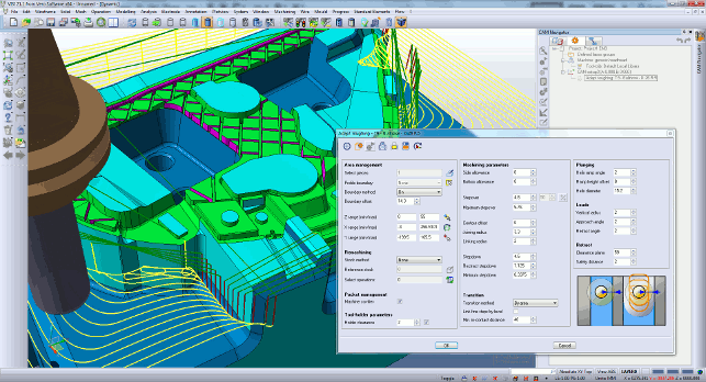
VISI 21 has an updated CAM interface for power users which presents all of the options and variables for an operation in a single dialog
During the simulation the axis positions, status variables, offset and other parameters can all be monitored and checked. Importantly, the processing times can be realistically computed, accurately reporting the processing times for each tool and each machining program.
Wire-EDM
Within the mould and die industries, Wire Electrode Discharge Machining (Wire EDM) is a common manufacturing process — it allows the creation of complex and often fine detailed features that would be difficult, if not impossible, to machine with traditional cutters.
VISI has supported Wire EDM for many years, but the VISI 21 release introduces a new ‘Smart’ operation that eliminates the need for the user to assign a specific 2 or 4 axis operation to a feature.
The cycle creates the simplest NC code by analysing the upper and lower contours of a feature and applying the most efficient toolpath. For example, if a 4-axis feature can be machined with 2 axis NC code then the smart operation will intelligently decide this.
Another key point to highlight is that VISI 21 fully supports AgieCharmilles machines with HMI controllers. The technology information is read directly from the AgieCharmilles EDM Expert software, which means the operator can now fully program the machine, including technology, in an offline environment.
Consolidating toolpaths
One thing that’s worth discussing is that alongside all of the changes, updates and enhancements we’ve discussed, VISI 21 also sees the company embark on a pretty long term project to consolidate the toolpaths of choice across all of its products to produce a multi-discipline CAM engine — remember, we’re talking VISI, Surfcam, WorkNC, Edgecam, Alphacam.
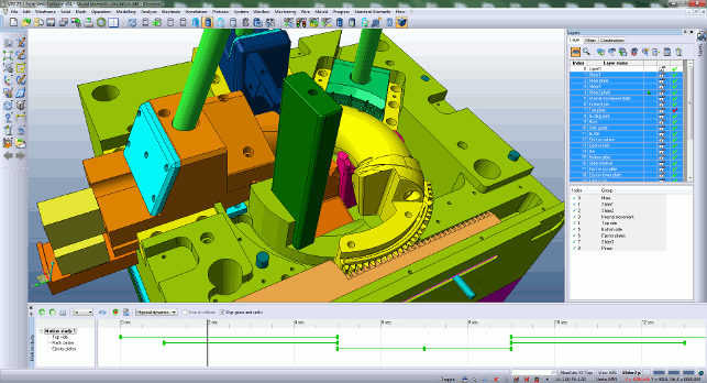
This release also introduces easy to use kinematic tools with an animation timeline
The development team is working to find the best toolpaths amongst that wealth of knowledge and you’ll see the same consolidation across all of these products where appropriate.
It’s also worth noting that for many years, Vero has been OEM licensing its toolpath libraries, and others within the industry will benefit from this technology consolidation.
Conclusion
VISI is a comprehensive set of tools for designing and manufacturing complex products in the mould and die industry (though it is seeing adoption elsewhere) and has the tools that industry needs.
From handling complex but dumb geometry, through machining preparation to programming machining operation and simulation.
As part of the Hexagon group, it’s going to be interesting to see how the system grows and how the consolidation across that product range is going to pan out in the coming years.
Also the interesting thing happening in the CAM market is how pricing is shifting.
Looking at VISI 21, it’s clear that the company is seeing this too and some of the more advanced, typically greater priced cost options (such as machining complex pockets in 2.5 axis as well as full gouge checking against 3D fixtures) are now available in two axis modules.
This makes it more affordable for those that don’t need the highly complex capabilities but want to operate efficiently.
| Product | VISI 21 |
|---|---|
| Company name | Vero Software |
| Price | on application |