

The Solid Edge 2020 release covers a pretty wide swathe of the system’s capabilities, extending existing tools and introducing a few new ones as well. So for this review, let’s start with the most widely applicable updates for this release, before investigating the more specialist or niche areas. With that in mind, a good place to begin is with a subject that everyone is familiar with – sketching.
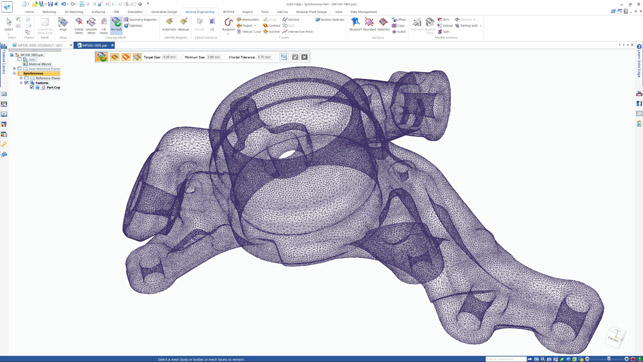
The new remesher makes light work of complex and dense meshes
While Solid Edge’s sketching capabilities have been consistently in line with how any CAD user would expect the system to work, that doesn’t mean there’s no room for improvement. For this release, sketching gets autoscaling and some new patterning options.
Autoscaling is a curious feature because once you see it work, you realise that CAD systems should always have worked this way. When you’re laying out a sketch, you’ll typically sketch out the lines, circles and arc you want, fairly roughly, and then apply dimensions to firm things up.
Only a pervert would do anything else. The issue is that, in most systems, unless you’ve sketched to almost precisely the right scale, when you go to apply that first dimension, you can blow out the whole thing. It then takes 10 more minutes to work out how to do it properly.
With autoscaling, as you add in that first driving dimension, the entire sketch scales to meet it, meaning your geometry remains in approximately the right shape, without requiring you to wrangle it all back into place. Autoscaling is switched on by default, but to be honest, I can’t see why you’d want to switch it off again (although you can of course choose to do just that).
On the patterning front, you’re now able to pattern sketch elements (not just reference points) in both circular and linear/rectangular patterns; you have control over angle (to rotate a pattern during creation); and more interactive previews, which show you results more clearly (particularly useful when patterning more complex features where orientation is key).
Solid Edge 2020 – Sheet metal & nesting
The part modelling tools haven’t seen a great deal of work done for this release – the existing tools are pretty rich and mature, covering solid and surface modelling, using both traditional, history-based approaches and the more direct synchronous technology techniques.
What has seen some work is the sheet metal environment. Solid Edge has always had a strong reputation for sheet metal design and documentation, but this release sees some important enhancements. One such area is in the construction of lofted bends, as are typically found where you’re looking to transition between two shapes; for example, from a cylindrical duct to a square vent or outlet.
For some time now, Solid Edge has allowed you to model up these forms and have in place ‘hit’ lines on the surfaces, but only now does it allow you to also carry out a full conversion of them from analytic surfaces into a series of flat, connected profiles that can be laser- or plasma-cut and folded in a single piece.
Solid Edge 2020 updates the tools already there to allow much more control over the conversion process, affording you not only a mix of automated and manual controls, but also more freedom to define how these rounded forms should be converted into flat sections. For example, you can define how many bend lines you want and control chord height, maximum segment length and angle. There are also more advanced controls over how bend relief is added (with trimming options), as well as support for documenting these forms in drawings, with bend tables that allow you to fully prepare fabrication documentation.
Elsewhere in the sheet metal tools, there’s a new option for dealing with instances where bends (particularly on thicker gauge material) would cause bulges at the edges of parts. While the system doesn’t let you model these, experience will tell you where they’re likely to occur, so at these points, the new Bend Bulge Relief command will let you insert a relief feature to those bends in circular and ‘U’ or ‘V’ shapes on the bends that need it.
Perhaps the last sheet metal-related update discussed here should be the new 2D Nesting add-on module – something that for some time now, Solid Edge has been crying out for. This will allow you to bring together all of the parts you need to nest in a production run (be they native Solid Edge parts, or imported DXFs), define the sheets you have available and have the system work through a nesting algorithm that will match your parts to the sheets available (using multiple sheet sizes in the same job).
It’ll nest parts within space, within other parts and more. Once you’ve got that data, you can then use it to feed into your laser, waterjet or plasma cutter software.
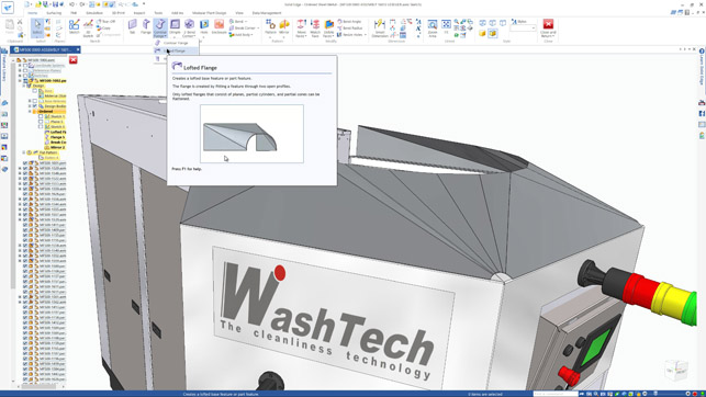
There are now a whole host of new tools for building manufacturable complex sheet metal forms using the lofted flange operation
Solid Edge 2020 – Assembly modelling & performance
Assembly performance is something that every vendor involved in mechanical design focuses on in every release. Why?
The simple answer is that as soon as these systems catch up with how hard their users push them, then users push even harder.
For the Solid Edge 2020 release, Siemens’ team has developed a new, high-performance large assembly mode set of tools that will apply best practice depending on your part count.
These best practices are focused on both display (such as shading, tessellation of models), as well as interaction (selection highlight glow), hidden edge display and will switch off those that most impact performance. There have also been a few tweaks made to how the system handles dragging and dropping components from Pathfinder, Solid Edge’s assembly structure browser. It’s a quick way to add in multiples of the same part, but sometimes the system would experience a little lag, causing the system to add in unwanted duplicates.
The last assembly-related update is not associated with creating or editing assemblies, but rather searching for components within complex assemblies.
The existing query select tools have been enhanced to allow you to use any of the metadata associated with your data as the basis for a search, such as name, keyword, material, creator and so on.
Solid Edge 2020 – Meshing modelling & reverse engineering
If you’re a current user or have been keeping up to date with Solid Edge’s most recent developments, you’ll be aware that the team has been focusing on greater integration of mesh-based geometry into standard ways of working and allowing users to perform operations on meshes just as they do with solids and surfaces.
While much of this is covered under the ‘convergent modelling’ technology label, it has also meant that Solid Edge has received a lot of additions, in terms of working with mesh-data to repair and repurpose it before you even get to the convergent type operations. These are proving useful to many users I’ve spoken to recently, and in particular, those regularly working with laser scanning and other reverse engineering processes.
If you’ve worked with the results of laser scanning, then you’ll be aware that the resultant datasets, even when decimated in post-processing systems, are typically quite large and as such, represent a challenge for most 3D design systems. While Solid Edge will allow you to open these up and work with them (within your workstation’s memory limits), it’ll be heavy going. To help combat this, the new remesh tool is going to make this process much easier.
Based on remeshing technology originating elsewhere in the Siemens stable (specifically, CD-Adapco’s StarCCM product), the new remeshing tool will rebuild your mesh according to the requirements/options you have set.
There are controls over target size (for facets), and how you want the system to maintain certain features, such as sharp edges and boundaries, as well as how the system handles areas with rapid curvature change (so the system refines the mesh, adding more facets to more accurately rebuild that area).
Whether you’re looking to simply reduce the size of the mesh, or to gain a more consistent mesh (useful for simulation or for downstream processes such as feature recognition), this will be useful to many.
Elsewhere on the reverse-engineering front, there’s a new tool that I wish every vendor would include, as it solves the ageold issue of reverse-engineered data not being in a sensible, orderly, co-ordinated space, making it more difficult to work with when you need to integrate it with other geometry.
Solid Edge 2020 introduces a Mesh Align tool that allows you to rectify this in a couple of ways. You can move and align a mesh using either a principle set of axes; a best-fit bounding box; a custom bounding box (which allows you to orient it to align better with the part’s geometry and your needs); or using geometry references to selection a coordinate system’s origin, then X, Y and Z references.
When you combine this with the region extraction tools that identify planar, cylindrical faces and so on, then you’ve got a nice workflow for making your mesh objects more sensible and usable.
The last item that we’ll cover on the mesh modelling front is going to greatly assist with reconstructing models or taking references from meshes by giving you a quick method of placing a section sketch (or multiples thereof) through a model.
Essentially, you choose the position (and direction and spacing, if you’re creating multiples), and the system creates a section through your model and will create a standard section which can be reused as needed. It’s worth noting that this works on both meshes and solids and, where appropriate, will recognise lines, circles, arcs and ellipses.
3D model compare
A new addition for this release, the 3D Model Compare tool comes at a time when engineering organisations are looking to work smarter with their data and reduce complexity. Essentially, it allows you to load together two versions of a geometry model file and perform a comparison.
Assuming that the two parts are in the same coordinate space, it’ll give you a visualisation showing how the two differ and where those differences are found – both in terms of additional and removed material.
This is a pure geometric comparison, rather than inspecting build history or metadata, but it’ll prove useful, particularly if you’re using geometry-based search to narrow down duplication of work or finding areas where stock count can be reduced.
If you want to formalise your findings as a report, then you can automatically generate a basic output from the system, with images already in place.
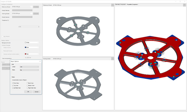
3D Model Compare will give you visual feedback on the differences between two parts
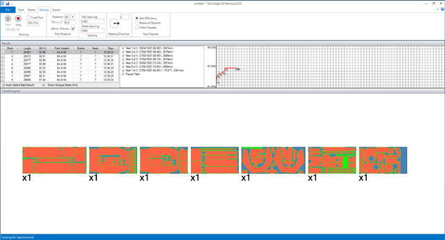
The new 2D nesting add-on will be a godsend for those who are already using Solid Edge’s legendary sheet metal design tools
Solid Edge 2020 portal & Augmented Reality (AR)
The final update we’re going to cover is the addition of a new 3D model visualisation method, built into the Solid Edge Portal.
If you’re not familiar with the portal, it’s a free-to-use project collaboration service that Siemens offers.
You get 5GBs of storage, integrated model viewing (based on the same HOOPS3D technology from TechSoft3D that other systems like this use), and collaboration (viewing, mark-up, commenting and so on). This has been extended for the 2020 release to include augmented reality (AR).
Essentially, it allows you to upload your model to the portal and generate a QR code (Remember, most smartphones automatically decode these with the camera now, so no special reader app is required).
You can share it with those who need it and scan it with your smartphone/tablet using the Solid Edge Mobile Viewer app.
This should then show the model in 3D, in situ, linked to the QR code, allowing you to view it at near-1:1 scale.
We haven’t had a chance to test this out yet (it hadn’t been released as we went to press), but it looks in line with similar offerings from other vendors. If you’re looking to take Solid Edge data out to external AR/VR systems, then it’s also worth noting that Siemens has added OBJ support too, which will prove useful for third-party visualisation systems.
In conclusion
We’ve only covered the updates made to the core of Solid Edge for the 2020 release, but there’s a whole lot more in store. There are new additions to the simulation tools (with the fluid flow simulation tools, in particular, getting some attention), and to the manufacturing, technical publishing and PCB/electrical related add-ons for the system.
As I stated at the start of this review, what this amounts to is a wide spectrum of updates that add new functionality and enhance existing tools. That said, there are certain updates in 2020 that make huge sense, to the point of leaving you wondering why these aren’t standard in every design tool (in particular, I’m thinking of autoscaling in sketches and mesh alignment).
Elsewhere, the Solid Edge team is demonstrating its eagerness to innovate and its willingness to take advantage of technology from other areas of the Siemens product stack.
As ever, if you’re looking for a 3D design system that offers you a deep and rich set of mature functionality, then Solid Edge is just as worthy of further investigation as it was two decades ago. The good news is that, over the intervening period, the system has continued to grow, to become something of a hidden gem.
| Product | Solid Edge 2020 |
|---|---|
| Company name | Siemens |
| Price | on application |


