QuickSurface – Tools for efficiently working with mesh-based data from 3D scanners are few and far between and can often be costly. KVS’s new product looks to change that
We have never been better off for solutions designed to capture the physical world in digital format.
At one time, the world of 3D scanning relied on high-cost hardware from a limited number of specialist vendors. More recently, the options have widened. There are now more vendors, offering more kit at lower price points.
With this expanded range of options come plenty of choices for buyers, in terms of accuracy, resolution, method and more.
Buyers can now spend from a couple of hundred quid for a depth sensor-based device to tens of thousands on metrology-specific scanning equipment.
What’s interesting is that while the hardware has opened up in terms of affordability and accessibility, the software world has yet to follow suit.
While more folks than ever before are accustomed to working with mesh-based data, the ability to take a point cloud derived mesh and turn it into useful surfaces for use in a CAD system still remains the preserve of costly specialist software from the likes of 3D Systems (with its Geomagic Design X and Wrap systems) and Innovmetric (with Polyworks).
Yes, some more mainstream systems are becoming more ‘mesh aware’. Some are even including editing, repair and resurfacing capabilities – but these are by no means heavy-duty enough to handle serious work on complex scan datasets.
So as it stands today, we face a road block in the path to wider adoption of 3D scanning and physical form capture.
Hardware prices may be decreasing and the kit itself becoming more accessible, but the ability to do meaningful work downstream with the data created remains hampered by a lack of similarly affordable, usable software.
Into this gap has stepped KVS, a Cambridge-based company founded by Kostadin Vrantzaliev. Vrantzaliev has, at various points in his career, worked on the development of SolidWorks and 3D Scanners’ Kube Software (which is active in point cloud-based inspection.) Those within the Rhino community might perhaps recognise the KVS name, meanwhile, for its Mesh2Surface plug-in for Rhino. This allows them to take a mesh-based data file and use a mix of polygon segmentation, surface fitting and quad-surface modelling techniques to reconstruct the analytic geometry from meshes as needed.
Recognising the market potential for a standalone version of this, Kostadin began development on QuickSurface in the last few years and the first release is out now. The overarching goal of QuickSurface is to provide a set of tools that allow you to take a mesh-based file, typically from a 3D scanner, and turn it into a set of surfaces that can be reused downstream in any CAD system.
The reason I use the term “set of surfaces” is that this is a process that has a wide range of requirements. Those requirements, moreover, will change from model to model, and from job to job.
For example, it might be that you have a polygon mesh of a scanned part and just need to be able to extract a few key surfaces in order to build mating parts or to take measurements from or work up the remainder of the part.
At the other end of the spectrum, you might need a fully patched-up and healed surface model that closely matches the 3D scan. The chances are that most jobs will fall somewhere between these two extremes. So let’s dive in and see what it can do, shall we?
QuickSurface in use
QuickSurface begins, as you would expect, with the importing of a mesh file resulting from your 3D scan process, typically in STL or OBJ. Once this is done, you can get to work, assuming that you’ve got a reasonably sized dataset.
It is typically the case that 3D scanning devices generate point clouds (and inherent meshes) that contain a great deal of data.
That’s useful if you want an intricate mesh, of course, but in order to be able to do something useful with it, it’s also entirely possible to reduce the number of triangles greatly and still maintain the accuracy and resolution of your data.
QuickSurface includes a tool to do just this. We tried it with some pretty hefty datasets and while the system was capable of working with data ‘as imported’, using the decimation tool made things much more efficient.
The next step in your workflow will depend on the task you want to accomplish, so we’ll break the system down into its various areas of operation.
A good place to begin is alignment. When 3D scanning hardware creates data, it does so only with respect to how the scanner is positioned in relation to the object, rather than the more ordered approach we prefer for 3D design.
As a result, unless you’re really lucky, your STL data will be at an arbitrary position in 3D space. The alignment tool allows you to reposition your scan, so it’s aligned with a more useful XYZ coordinate system. This pays dividends, both when using the system further, as well as importing the resulting data into your downstream CAD system.
There are several options here. The first is to apply a known rotation or translation to your mesh data. Unless you’re really lucky, this is going to mean eyeballing the whole thing. The other option is to use references from your model to define axis directions and references.
A more sensible way to do this is to use QuickSurface’s tools to add in primitive surfaces that match to readily identifiable features, using a mix of cylinders, planes and spheres. To do this, you need to explore the mesh selection tools in the single toolbar across the top of the screen.
Hitting the ‘mesh selection’ icon brings up a palette of selection methods, allowing you numerous ways to grab the triangles you want, whether that’s using a simple painting method, lasso, curvature-based finding or some other method. You have control over the size of selection brush and can also remove faces from selection just as quickly.
As you can see from stage 4 in our workflow below, it’s relatively simple to grab the faces of the plane. Then you hit the Primitives icon and add in a plane that conforms to these selected points.
This can then be used as the reference for aligning your mesh. While we’re on this subject, let’s move on to other geometry fitting tools in the system.
Alongside the ‘fit plane to faces’ option, planes can be defined at a specific coordinate position and rotation value, offset from other existing planes or fitting as a mid-plane two other planes (this is really hand for defining symmetry for reasons that will become obvious later on).
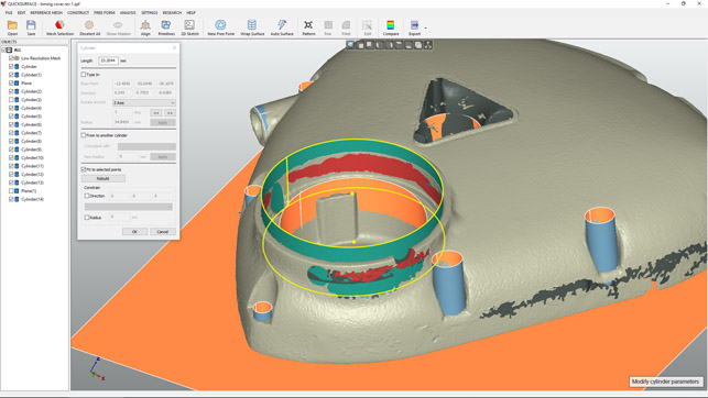
There are also tools to fit cylinders and sphere to geometry, too. The cylinder tool is particularly useful if you’re looking to build precisely mating components from scan data. It allows you to select the faces of the cylinder to fit to, then fine tune it in terms of alignment, radius and so on.
There is also a sketch extraction tool that allows you to create a section plane and create sections through your model.
This could be a single sketch, used as the basis for an extruded surface, or a number of sections to build a loft (you’ll do this in your CAD system, since QuickSurface doesn’t have these tools at present).
While these primitives are useful in many engineering workflows, chances are you’re going to want to extract more than those types of geometry from your scanned data – and there are more complex options available in QuickSurface. These centre on the creation of freeform patched surfaces and can work either in an automated manner or using a manual method. Let’s explore both.
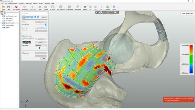
Fig. 2 The FreeForm surfacing tool allows you to quickly build on a patchwork of surfaces to describe your model’s form, giving constant feedback on deviation from the mesh
QuickSurface – FreeForm surface fitting
The creation of a freeform surface that fits across the entire surface of a part, unless it’s very uniform and very simple, is always going to be complex. What QuickSurface does is offer up two methods. The first uses a surface patch fitting process that gives you control over the number of patches used (we’re talking hundreds, if not thousands), the accuracy required and how the surface patch adheres to sharp edges. This is called Auto-Surface.
In practice, this is a brute-force approach, but if you need to take your scanned model to a CAD system quickly, it gives you a good place to start, if in a rather heavy-handed manner. The reason is that, for non-trivial datasets, you’ll need to give the system the allowance of enough faces to accurately skin your part. During our time with the system, we found that this approach was best suited to organic, more freeform parts, rather than heavily prismatic components, as there are issues around fitting surface patches around sharp edges and the like.
There is also a Wrap Surface. This is similar to the auto-surface operation, but uses a cylindrical set of faces, which are then wrapped to the selected portions of the mesh. While this is a pretty specific tool, it’ll prove really useful if you’re looking to skin across the surface of spars or forms cylindrical in nature (see our example in Figure 3 of a tibia).
The last option (and probably the most useful) comes in the form of manual freeform patching tools. Essentially, QuickSurface allows you to sketch in a surface patch layout (using four-sided or quad surfaces) that snaps control points to the surface of your mesh.
You can do this in a couple of ways: you can either start with a small patch and grow it outwards (there are nice on model interactions for adding additional faces), or create a gross large patch and then refine it. The former is a much easier way to retain control over the process, but for larger parts, the latter might be a better approach.
Whichever approach you use, once you’ve learned the ins and outs of this workflow (there are some excellent tutorial videos on YouTube), it’s pretty easy to patch up a surface and create something useful.
While this is just the first release of the system, there are nice workflows in place and all of the controls you need are in simple, well-documented dialogues and right-click menu items.
As you can see from Figure 3, it’s pretty simple to start patching the surfaces you need, grow your surface patch and ensure that you’re within tolerance at the same time.
To add in another patch, you select the edge you want to grow from (or multiples thereof) and a small ‘D’ pops up. Drag from that and you’ve added in a new string of faces. A quick tidy-up of your control points and you’re ready to start again. It’s a nice workflow that has enough flexibility and control to ensure you’re getting the data you want, rather than the data the system thinks you want.
Alongside these raw geometry modelling tools, there are also a number of editing tools to help tidy up and build additional features. For example, a number of the operations have symmetry controls built in, so you can define a plane and have the system build a mirror of your surface patches.
Another is the pattern feature. This is super useful for many reasons, but one workflow which springs to mind is the scanning of axisymmetric parts, such as pulleys, rims and so on. With good patterning features, you can save time by just scanning a single instance of that pattern, constructing the geometry in QuickSurface, then using the pattern operation to create the whole. All in all, that amounts to a lot of time saved across the whole process.
There are also trimming tools to help cut back some of those surfaces you create to other geometry, as well as a filleting tool to build in those types of features – all of which can be checked and compared against the original mesh at any time using the compare tool. This will give you a graphics display of either a graduated measure of deviation of the surfaces from the underlying mesh or a pass/fail against your supplied tolerance.

To enlarge image click here
Exporting your data
Whether you’re surfacing up a small portion of your scan data or looking to reverse engineer the whole part, you’ll eventually end up with a set of data that you want to export to your CAD system. At present, there isn’t a reliable way to export both the mesh and surface data as a single entity, so QuickSurface handles both separately.
On the surfaces front, you can export them as either a STEP or IGES file. On the mesh front, you can export either your original mesh or the reduced/decimated file as an STL file.
The latter might seem an odd choice, as you have the data already, but consider that if you’ve used the align part and mesh decimation tools, you’ll have a mesh file that’s in both a different position in coordinate space and much more lightweight. After all, CAD systems typically struggle with raw output from laser scanners due to the heaviness of the point clouds and the inherent mesh files.
There is an additional option using KVS’ QSconnect which currently connects your QuickSurface to SolidWorks. This isn’t a simple export of data and rebuild inside Solidworks. Instead, it guides you through the process, taking your data, built up from a set of operations inside QuickSurface, and transfers them step by step to Solidworks.
Once the two systems are connected, you’ll start to see Solidworks build the individual surfaces in the same manner as QuickSurface, building a history-based model of each operation.
Because this can be an error-prone process, you can instruct QuickSurface to pause the process when trim operations are used, so you can double-check that Solidworks has carried out the operation correctly. Compared to normal export/import workflows, this might sound like a time-consuming process, but the result is a much more robust model.
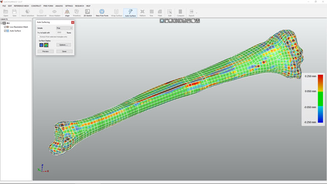
Fig. 3 QuickSurface’s AutoSurface tool is excellent for quick surfacing models, particularly when they’re more organic in nature, such as this tibia from an STL derived from CT scan data
In conclusion
It’s not that often that we get to take a look at brand-new software these days, so spending some time with QuickSurface was a delight. The developer’s background across the CAD industry, as well as providing tools for Rhino, really shines through.
QuickSurface is one of those applications that’s likely going to prove useful to many, particularly as 3D scanning becomes more accessible and workflows become more entrenched in our design and engineering offices.
Perhaps its brilliance lies in the fact that it doesn’t claim to do everything – there are no point cloud clean-up tools and there’s no mesh editing, per se.
Instead, QuickSurface is about taking your mesh-based data out of your scanning process and achieving the geometry you want. Whether that’s a complete part, skinned and surfaced up, or a select set of reference surfaces from which you will begin to design another part, QuickSurface handles these tasks in a very efficient, clearly defined and well executed manner.
There’s are also some interesting things to consider around price and competition in this space. While every hardware vendor has their own solution and bundled software, there are often hefty add-on prices for software to do this type of work.
In fact, these can often be more expensive than the hardware itself.
At €1,995, the starting configuration of QuickSurface Freeform contains everything we’ve discussed here, except for the surface fitting tools and the SolidWorks connection. Adding these in bumps the price up to €3,995.
QuickSurface offers an entirely viable alternative in a market that one vendor, in particular, has had to itself for a long time.
What’s more, it delivers this capability in a very competitive price bracket much more closely aligned with the mid-range scanning devices now available.
| Product | QuickSurface 1.0 |
|---|---|
| Company name | KVS Ltd |
| Price | from €1,995 |