Geomagic is well known in reverse engineering circles as a software provider that assists with taking scanned data and preparing it for use downstream — whether that’s for design or inspection.
A couple of years ago, Geomagic was acquired by 3D Systems, which around the same time also acquired its fiercest competitor, Rapidform.
Now, with both under the 3D Systems banner, these two competing products have started to merge, combining Geomagic’s focus on wrapping surface data to complex scans with Rapidform’s ability to reconstruct history and feature geometry from the same.
While these standalone systems continue, the company has just unveiled its first foray into the world of CAD system integrated plug-ins with the release of Geomagic for SolidWorks.
User experience
Being a SolidWorks integrated plug-in, the Geomagic for SolidWorks user experience will feel familiar to many users. It has its own Ribbon toolbar and follows a linear workflow, from left to right, providing all of the tools and operations in a logical order, depending on the task at hand.

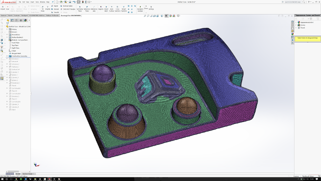
Geomagic for SolidWorks covers the whole workflow from scan to feature history reconstruction, including region identification as shown here
Scan to part workflow
When it comes to your data, you have two options. You can either import the data from an existing scan or external system (via STL, PLY or OBJ) or you can use the Scan option to connect to one of the many leading scanners including those from Creaform, Faro, Hexagon, Nikon, Vialux and the Capture scanner from 3D Systems.
Whether you end up with a point cloud or an imported mesh, the final result is the same; a set of data that’s dumb and facetted. If you want to push that data into more detailed engineering and use it for downstream design work, then you need to convert it into surfaces — which is where the rest of the tools come into play.
The first point of call is to repair the mesh. Here, Geomagic for SolidWorks includes tools to remove common issues, which range from smoothing out the mesh, removing any spikes or other extraneous data to hole filling and remeshing.
Of course, these are available in both an automated manner, which rips through all of the checks and tries to fix up the mesh as best it can, or you can work through each tool manually. The latter is particularly useful if you’ve only got a partial scan or only want to focus on a specifi c part of it. The system loads the mesh and allows you to work with it, using SolidWorks’ display and interaction tools as you’d expect, with some tweaks to make the selection of facets easier.
Once your mesh is in a good state, you then need to make a decision about how best to approach the conversion process from mesh to BREP model. For this there are two key approaches.
Surface wrap
The first, which is a brute force approach, uses the intelligent technology from Geomagic Wrap to wrap a set of surfaces around the model to provide you with a result.
Depending on your geometry and requirements, this might be perfect or it might be an overly complex and heavy set of surfaces.
There are controls over the number of patches, but even the most simple part could result in hundreds of surface patches. This will then have a detrimental effect on any downstream processes you want to apply (think shelling a solid that contains 1,000+ surfaces — that’s going to be tricky for any system).

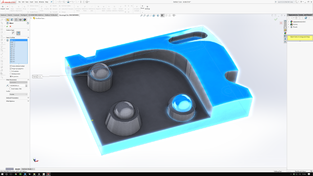
A combination of Geomagic for SolidWorks mesh-related tools and SolidWorks’ native modelling tools is used to reconstruct the geometry as a native, feature and history driven part
Model reconstruction
The second approach is to use the reconstruction tools.
This provides a set of operations that allows you to build up features (as you could in a standard history based model in SolidWorks) using references where required from the mesh.
One of the first steps is to carry out a regionalisation of the model. This will recolour the mesh according to planar relationships and curvature. As depicted in Figure 1, this provides clues as to how the model needs to be handled — and these regions can also be selected where appropriate.
There are a number of primitives as well as more freeform surface options here. You can use the built-in tools to align the mesh to a local co-ordinate system and set of planes (which will make life much easier). A plane of symmetry can also be added to reduce the modelling time where appropriate.
If you’re looking to extract sketch data from the model, there are tools to add in a sketch plane, extract a section, and then use that data as the basis for your sketches. If you’re using primitives, there are automatic filtering tools that allow you to use portions of the mesh as references.
For instance, cylinders can be added by selecting a set of faces on the axis you want, then selection references used to defi ne the start and end limits.
Essentially, it’s a mix of taking references from the mesh geometry and using intelligent selection tools, all combined with SolidWorks’ native modelling tools to work up the form of your model.
This process is much more time consuming than the auto-wrap approach, but the results will be a more intelligent and lightweight model that is perfect for pushing into downstream processes.
Conclusion
Scanning hardware is becoming both more affordable and more widely used in many industries — and rightly so.
There are numerous use cases where a physical object needs to become part of the digital design and engineering workflow. The common issue is the time and effort required to take that scan data and turn it into something that can not only be referenced, but used as part of a downstream workflow or process.
What Geomagic for SolidWorks does is enable that to happen, directly inside the world’s most popular 3D design system and does so with all of the knowledge and experience that you’d expect from the folks behind it.
| Product | Geomagic for SolidWorks |
|---|---|
| Company name | 3D Systems |
| Price | $7,900 |


