Those that follow Autodesk Inventor closely will be only too aware that there have been many changes over the last couple of years. With the release of Fusion, many detractors were quick to sound the death knell for the more traditional, desktop-based Inventor.
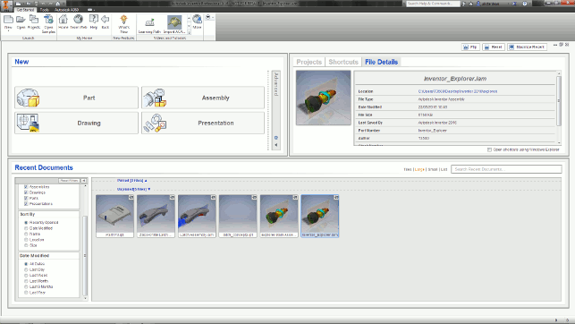
The new start window gives you a clear, search and filterable window into your current projects and data
New tools were added to Fusion that hadn’t yet seen light of day in Inventor and, in all fairness, development work on the latter seemed to slow somewhat in the last release cycle.
But the fact of the matter is that Inventor is still a flagship product, with a rich set of tools covering everything from mechanical design and engineering and drawing and documentation creation, to tube and pipe design and electromechanical integration.
So with Inventor 2016 now available, let’s take a look at some of the highlights of this latest release.
The changes are spread across a wide gamut of the system’s capabilities and functionality, but the first thing that existing users are likely to notice is a big change to the very first window the system presents to them.
In previous releases, they got a pretty bog-standard interface with part templates, access to either Vault (Autodesk’s PDM system) or local file projects, as well as lists of common tasks comand recently used files.
For 2016, this changes to a cleaner layout that presents projects and data in a more usable form. Items currently in progress or needing attention can be pinned, making them immediately available, and there’s search and preview tools to help as well.
Imported data efficiency
Perhaps the biggest addition to Inventor for this release is the introduction of new data import tools.
While we’re all used to working with geometry files that come from other systems, the issue lies in how they’re converted. Typically, the host system reads the files from the third-party system, does a conversion and then stores that data in its own native format, from which the user then works.
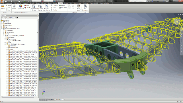
Inventor’s new tools for working with imported geometry let you maintain a link to the originating data — in this case, from Siemens’ NX
While this is acceptable for a single pass, when it comes to handling design changes (an inevitability on most projects), it’s not so smart. With changes, the whole process needs to be re-executed and any subsequent work redone.
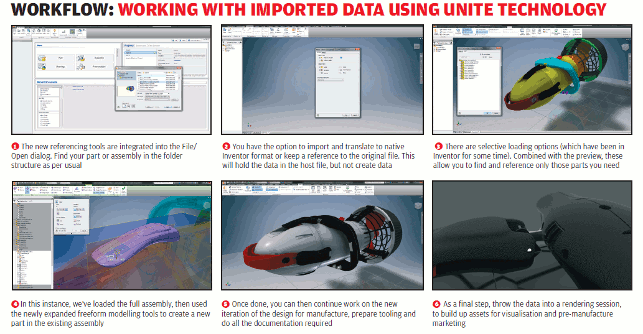
What Autodesk has built into Inventor 2016 is the ability to reference third-party files and work with them, without having to convert the files into a native file format. Autodesk is referring to this as its AnyCAD technology.
This shouldn’t be construed as removing the translation process entirely; instead, the system does the translation in the background and maintains a link to the originating data.
As a result, you end up with far less data being created, which cuts down on management headaches, and, if the reference data happens to change, you can reload it and work with it in a much more efficient manner.
In terms of how it works, the process is pretty much standard: you invoke the import process, either by opening from scratch or placing a part or assembly into an existing assembly.
The system then presents you with the option to either convert the geometry or to use the reference method with the usual controls over which entities to import (such as solids, surfaces, work features and so on).
The reference method then loads in the geometry, performs the conversion and presents you with the data. What it doesn’t do is create any native Inventor data on the disk. Subsequent changes to data will be updated whenever changes are detected.
There are also options available to select geometry; these allow the user to pre-load the assembly and to find the part file or files that they need and just load those — again, maintaining the link back to the originating geometry.
At this point, it’s worth discussing what the user can do with this data. If you’re placing the geometry for reference purposes, you’re pretty much good to go.
The geometry can be measured and referenced in terms of geometry creation from your other parts.
In terms of handling design change, this approach is not going to work each and every time. CAD systems use entity references to track where geometry has moved, which is why design changes that don’t change the topology of a part will tend to be more successful than larger, more complex edits.
When it comes to editing that data, meanwhile, you will find that you need to break the link to the originating data and do a full, traditional translation, creating those native-translated forms of the geometry.
At present, Autodesk’s AnyCAD technology works with SolidWorks, Catia, NX, Creo (Pro/Engineer), as well as with Alias files.
Complex shape design
Those that have been paying close attention to the development of Inventor will also be aware that, in the 2015 release, the product started to see some of Autodesk’s T-splines technology included for sub-division (or SubD) modelling.
This technology was acquired by Autodesk in 2011 and has since been developed further in Inventor’s cloud-based cousin, Fusion 360.
The Inventor 2015 release was the first time that T-splines capabilities had been included and those users that have played with both Inventor and Fusion will know that this Inventor release didn’t feature anywhere near the control offered by its sibling, with significant limitations in terms of what forms could be created, for example.
The good news is that the 2016 release addresses these shortcoming and users will see a whole range of tools on offer to push, pull, edit and refine complex shapes that would typically take hours of work to set-up and create using surface-modelling techniques.
If you’ve not used SubDs in a history-based system before, the workflow goes like this: you create the complex forms and these are then stored in the feature tree (in this instance, as a ‘freeform’ feature). You can have multiple base geometry sets which you can do a lot with, but ultimately, the goal is to have a manufacturable form.
Once freeform edits are complete, you exit the command and the system automatically handles the conversion of that subD geometry into a NURBS model. As you’d expect, this can then be run through further processes, such as shelling, creation of engineering details and so on.
The benefit of this integrated approach is that any edits can be made by editing that freeform feature and then further operations propagated.
Of course, there is an important caveat to this: due to the complexity of the freeform geometry that you can create, you need to be mindful that downstream features need to be able to work with it.
Sharp creases, for example, can wreak havoc with shells and making large-scale edits to geometry can cause your history tree to explode if you’re not careful.
It’s also worth planning out, in advance, how you’re going to create the forms you want. SubD modelling is incredibly powerful, but a common mistake is to try to model everything in a single set of geometry, particularly where you have complex changes in tangency and cut-aways.
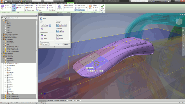
The 2016 release gives you more control over freeform modelling with T-Splines technology — it’s now on par with Fusion 360
A better approach is to use separate lumps of geometry and combine/cut/subtract them, rather than trying to do everything in one feature set. Handily, Inventor supports this way of working.
But with careful finessing, you can achieve beautiful surfaces without the headaches and effort typically associated with the design of such forms.
3D print support
This is an interesting area. With all the hype surrounding 3D printing over the last few years, we’ve seen most of the 3D design software vendors start to claim support for 3D printing processes and common workflows.
What’s interesting is that, in many cases, the results miss the mark by a pretty wide margin. After all, simply adding some fancy options to your STL output doesn’t really help the common workflows involved in the process — and that’s exactly why vendors that have really thought the issue through (for example, Materialise with its Magic system) are proving so popular among those users deeply engaged in 3D printing or additive manufacturing.
Autodesk differs from most in the CAD world (with the possible exception of 3D Systems as it now owns, at the last count, at least four 3D design tools), in that it’s already gained some significant experience in this area.
Since it released its Ember printer and launched its Spark platform, the company has been working hard to close the gap between 3D design and 3D print – and we’re starting to see the fruits of this work in its professional systems.
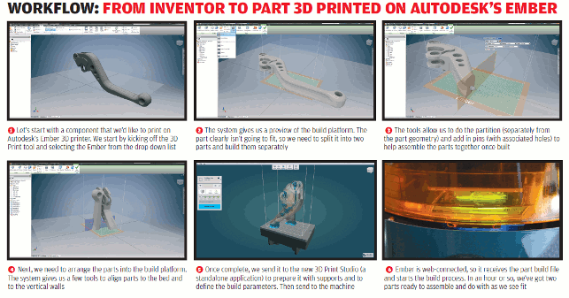
Introduced in Inventor 2016, a new 3D Print set of tools (in the Environments panel) is now available.
This isn’t just for scaling and preparing STL files; rather, it features tools that enable users to lay out their parts on the beds of a range of printers and use semi-automation to take larger parts, splice them and add features that allow users to connect them back together using pins and holes.
Then, if the printer supports the Spark platform, they have additional tools to pass that information out to the software. This will become more useful as more hardware vendors start adopt the Spark platform.
At present, the best example is still Autodesk’s own Ember. From Inventor, you push the data to an external application (Print Studio), add in the supports needed and send it to print. It also supports a couple of Stratasys, Objet, Dremel and Type A machines as well.
Sheet metal
Alongside all the fancy bits and bobs in this release, it’s also good to see some of the fabrication design tools get some attention. For sheet metal, the big ticket items are in two areas.
The first development is that it’s now possible to have zero-radius bends in your parts. This might not seem huge at first, but when you consider the reality that sheet-metal techniques are just as applicable to designing thin-walled parts as they are for parts that you put through a press brake, this development suddenly makes much more sense.
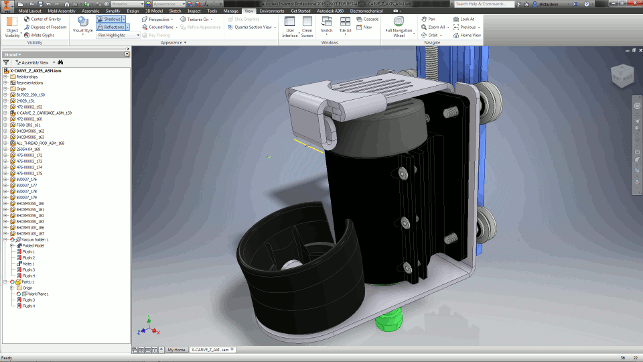
2016’s sheet-metal tools now include multi-body support, meaning more efficient data management and some nice tools to generate parts with more complex inter-part references
The second development is that the sheet-metal functions now support multi-bodies. In other words, they allow users to create single sheet-metal part files comprising multiple components, rather than forcing them to concoct an assembly and separate parts.
This will make taking references easier, file management less fraught and design changes faster.
Drawings
The last area of improvement in Inventor that we’re going to look at here (and there’s a stack more to investigate if you’re an existing user), focuses on drawings.
It never fails to surprise me how technology vendors in this space can find room to make the process even more efficient, but judging from Inventor 2016, it seems that there’s still room for innovation.
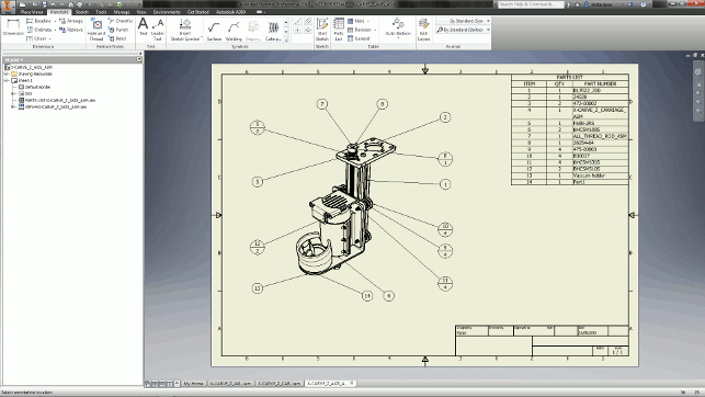
Drawing views are created in a dynamic manner, saving you from referring to a dialog and keeping you focused on the task at hand
One of the most fundamental changes to how Inventor’s drawing tools have changed is seen at the view creation stage. While previous versions relied on users interacting with a pretty complex dialog, much of this process is now driven from direct interaction in the window.
They’ll see handles and the familiar view cube pop up and these are both used to create the views they want and fine-tune them for scaling, orientation and so on.
This is pervasive across all of the view creation tools, including detail views, sections and more. It makes them easier to use and more dynamic; if you need to dive into the details, the same dialog is there, but it has been rethought and slimmed down a little.
Elsewhere in drawings, perhaps the biggest other update can be seen in the tools available for working with assembly drawings and the creation of balloons. These can be grabbed and aligned to suit whatever way you need them.
As we develop more complex assembly models, these types of tools will be invaluable to users looking to get through the annotation process quickly, lay models out and then dive into adding additional, vital details.
In conclusion
With the rise of Autodesk’s cloud-based design ambitions, users might be forgiven for expecting development to wane on the Inventor product set.
This release, I believe, shows that this is not the case at all.
Inventor has been on the market for a good ten years now. Its breadth of coverage is wide, its functionality deep — just as you’d expect from a system that has been on desktops for that long.
What’s interesting is that it’s pretty clear that the benefits of Fusion’s arguably faster-paced development is starting to pay dividends for Inventor as well.
Admittedly, many users might have been disappointed with the initial implementation of T-splines for complex shape description in the 2015 release. The good news for them is that this issue been addressed in 2016 and addressed comprehensively.
Elsewhere, the AnyCAD tools that ease the process of working with third-party data in other formats, while maintaining links to engineering information, will likely prove useful to many.
That’s particularly important when we consider Inventor’s increasing adoption in the supply chain. This is an area in where the ability to take customer data and using it as a reference for further work is an essential part of the process.
For many users, being able to do just that without a huge amount of rework when those pesky but inevitable last-minute design changes come in, will no doubt be warmly welcomed.
| Product | Inventor 2016 |
|---|---|
| Company name | Autodesk |
| Price | on application |


