
In the simulation software market, Ansys is a legend. For many of you, it will have been the first FEA tool you used at university.

Ansys R17 lets you take PCB data from a variety of formats, extract where the traces would lie, map them to a mesh and simulate them in a much shorter timeframe
It continues to be a market leader; it’s even considered to be the de facto standard for simulation at many organisations. And while the company’s reputation was undoubtedly built on its structural analysis capabilities, the last decade or so has seen Ansys – and its software portfolio – expand considerably.
There have been big acquisitions involving CFD technologies, such as the takeovers of CFX in 2003 and Fluent in 2006. And, at the same time, the company has built up a wide range of more special-purpose code, allowing users to simulate electromagnetic fields, for example, or cold flow in internal combustion engines.
It’s no surprise, then, that Ansys has been working to consolidate and centralise its core application set. Much of the company’s work here centres on the Workbench platform, with its graphically-led (as opposed to command line driven) interface that guides users through a dynamic process of simulation set-up, linking together the constituent parts of a study.
For run-of-the-mill tasks, this may not offer big benefits (beyond making the setup process clearer), but for more complex tasks, its strengths soon become apparent.
As multi-physics studies increasingly become the norm, Workbench is built to allow inputs or outputs from one study to be fed into another.
You simply drag a connector from the output of one process (for example, a thermal study) onto another (say, the loading conditions of a stress analysis) and the system handles the rest.
That allows you to combine results of different physics models in a way that previously would have been complex, time-consuming and error-prone.
Ansys R17 – PCB simulation
A big area of focus for Ansys Workbench R17 is in increased automation when it comes to setting up jobs that heavily feature PCB data.
The new tools make the process much easier — and PCBs can be tricky, because of the need to simulate the board itself, with its multi-layered construction, the traces that provide the circuitry and the components assembled onto the board.
With this release, the setup work done can be done in a few clicks.
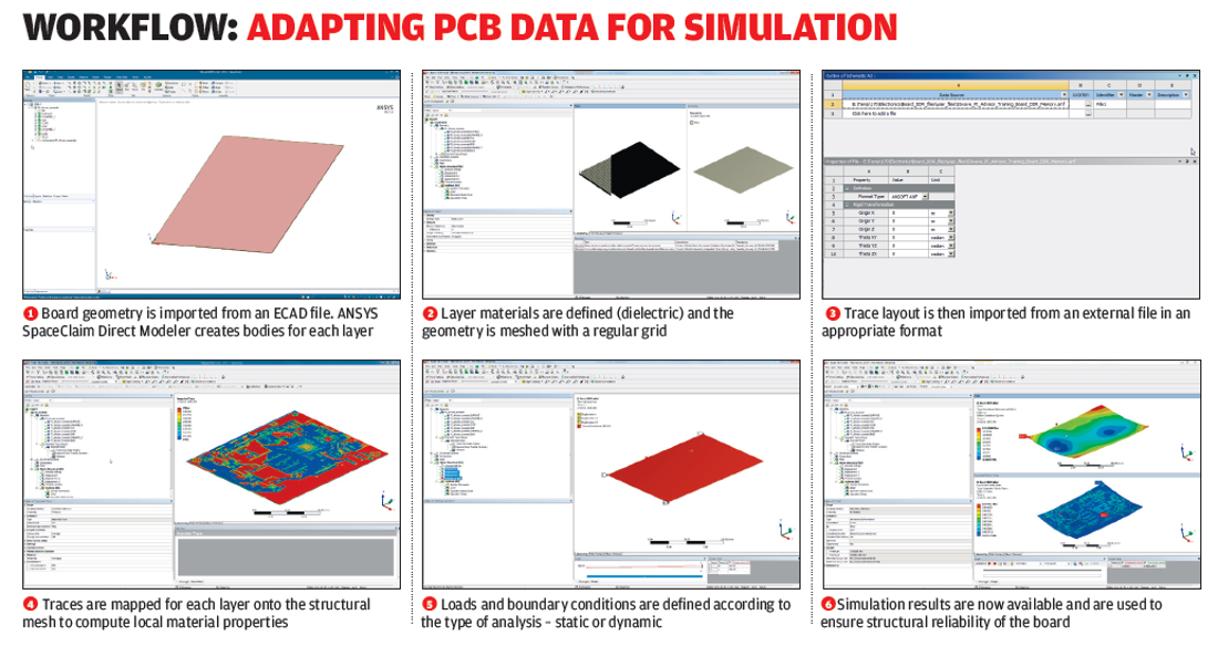
You begin with modelling the board itself. These are typically pretty standard and the same process can be applied to a flexible PCB just as easily as a rigid one.
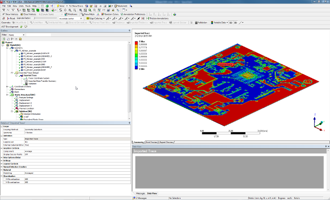
You then define each layer – substrate, copper and so on. The trace is then imported from a system like Mentor and the trace information is mapped onto the mesh in the FEA model.
The system then generates a mesh that allows it to represent each of the different materials in its elements.
As you can see from the image below, this can be a low-resolution mesh with quite coarse replication of those details. But it can, of course, also be dialled up, so that a higher resolution mesh is generated.
Either way, the mesh can then be used for a number of purposes, and can give you a more realistic view of how heat affects components and those around them. It can also become part of a larger system of simulations.
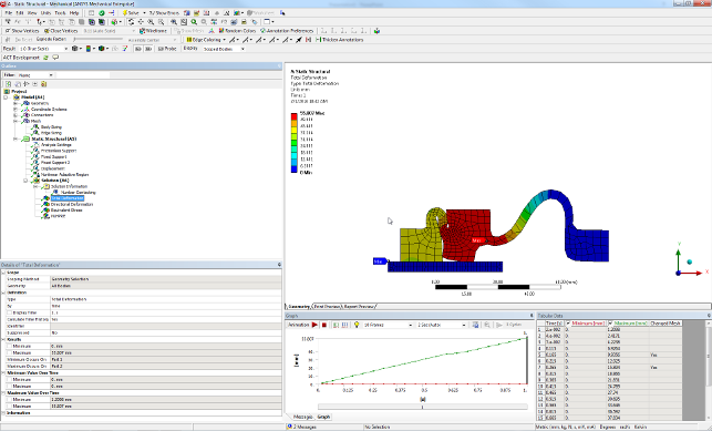
The adaptive meshing for large deformations lets you get closer to an accurate result, without the need for intermediate steps and manual adjustment
Ansys R17 – Handling deformation
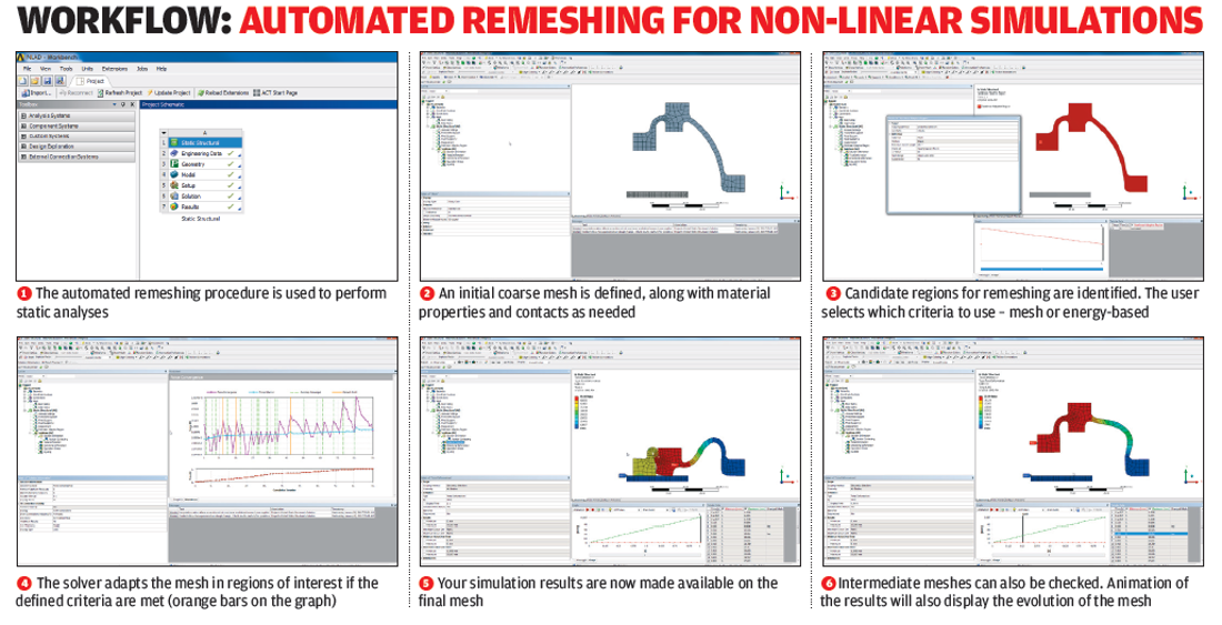
Another focal point for Ansys R17 is the process of simulating large-scale deformation of parts – specifically, within non-linear simulations.
Many of the problems here come down to the meshing of geometry. When a study is set up, the typical workflow sees the undeformed component used as the basis for the mesh.
Issues then arise because of the large-scale deformation of that component; in other words, the shape changes (and changes dramatically in many cases), so that the original mesh isn’t suitable for subsequent time steps in the study. This will impact subsequent steps and the accuracy of results.
By contrast, the new tools in Ansys R17 automatically monitor deformation and remesh the part at appropriate intervals, so that results remain consistent as the part deforms.
Also related to working with deformed geometry, there are tools that make it easier to take the geometry from one simulation and feed it back into another process.
For example, when you’re simulating the stamping process, you’ll start with clean, analytic geometry. Convert it into a mesh and the result will be a deformed mesh.
If you then want to use that deformed state in further simulation studies or push it into further design work (perhaps to assist with accounting for springback in the die, for example), you’re stuffed. It’s a mesh.
What these new tools can do, however, is take the original mesh and geometry as a starting point, then use the deformation of the mesh, map the deformation and use that to drive morphing of the original geometry to match.
To enlarge image click here
Ansys R17 – Crack modelling
Ansys introduced the sub-modelling concept a few releases back.
This allows you to take a chunk of a large, coarser mesh, rework the controls, mesh and boundary conditions and integrate that chunk into a larger whole.
It means that you can cut down on simulation complexity (and solve times), while maintaining the fidelity of results.
With this release, however, SpaceClaim (the Ansys 3D modelling tool that is tightly integrated with Workbench) can be used to create sub-model geometry far quicker than was previously possible.
In Ansys R17, SpaceClaim has been integrated into a new workflow to assist with modelling and pre-processing for the simulation of cracking – specifically, to compute crack characteristics, in order to find out if and how a crack might grow, rather than predict crack growth.
It works like this: the user starts with a large, coarse study to identify areas of stress concentration and users the submodelling tools to select a particular areas for further investigation.
They then model the crack geometry (based on experience, real-world instances or physical testing) and mesh the part at a resolution that’s appropriate for the sub-model.
When the sub-model-based simulation is complete, this can then be reintegrated back into the coarser mesh of the complete part, while Ansys handles all of the mesh and stress transference details.
Ansys R17 – Flexible vs rigid dynamics
Alongside its traditional FEA tools, Ansys also includes rigid body dynamics, which allow you to simulate stresses in more complex rigid bodies and use these as a driver for more detailed simulation.
Traditionally, you’d perform such a study on a part in which all components were rigid – a robot arm, for example. But as we know, in practice, this is rarely the situation and, with Ansys R17, you’ve now got the ability to define as flexible one or more parts in such as study.
What this means is that you can still carry out a formative rigid body study, but you can also add in a level of extra detail where needed. This will help with finding vibrations and other phenomena that might introduce stress in joints.
Faster model set-up
The last area we’ll cover in this review aligns closely with the overall theme of automation in the Ansys R17 release.
Ansys now gives users a set of tools that will enable them to automate the set-up process for frequently conducted types of study through the use of Python-based scripting.
The idea here is that, by using these scripts to automate common tasks, users can devote more of their time to focusing on the details of each study.
While it’s true that macros have made it possible to do this for some time, it’s also the case that scripts give you far more freedom.
At present, theses scripts need to be written from scratch, but the goal is for a set of tools that allow you to capture actions inside Ansys and use these as the basis for scripts.
Incidentally, scripts can be reused inside Ansys, or alternatively, can be delivered as a web page, without the need to interact with the process.
To enlarge image click here
Conclusion
Ansys R17 represents the natural evolution of work that its developers began a few years back.
But along the way, the company has continued to make Workbench a centralised point of access to all the tools in the Ansys family of products and a venue in which users can build up their simulation studies.
Now that the groundwork is laid, the company is focusing on streamlining some tricky workflows. While many of these were supported in previous releases, at least to some extent, they could still be troublesome and error-prone.
Ansys is also putting a lot of effort into automating tasks, making them quicker (as seen with the PCB meshing tools) and smoother (by hard-coding best practices directly into the system).
A perfect example is the automatic remeshing of parts during large deformation. We all know that materials can deform heavily within their elastic limits.
Essentially, it’s a linear material problem, but it’s one that, due to the nature of the deformation, is best handled using non-linear approaches. (Here, I could be tempted to bang on about stiffness matrices and their dependency on both material and geometry, but I will resist.)
These new tools automate some of the issues associated with this kind of work (such as incremental remeshing) and make simulation easier to use correctly.
To some extent, it achieves this by bridging the gaps in understanding that can exist between designers and engineers.
In summary, Ansys R17 moves the usability of the system onwards and provides customers with a single, connected and intelligent workspace, via which they can access an incredible range of simulation technologies.
| Product | Ansys R17 |
|---|---|
| Company name | Ansys |
| Price | on application |


