Credit: Oleksi Natykach/Shutterstock.com
As the world moves to reduce its dependence on fossil fuels, the global market for wind turbines is growing and is projected to reach around $70 billion dollars annually in the next few years.
While wind power on such a grand scale will be a great achievement, another powerful force of nature is preventing the industry from reaching its full potential: lightning.
Lightning strikes are the single largest cause of unplanned downtime in wind turbines, responsible not only for the loss of untold megawatts of power, but also huge operation and maintenance costs.
Wind turbines are particularly susceptible to lightning strikes because of their great heights, exposed locations, and large rotating blades. Lightning can wreak havoc, both directly and indirectly, on virtually all wind turbine components, including blades, control systems and other electrical components.
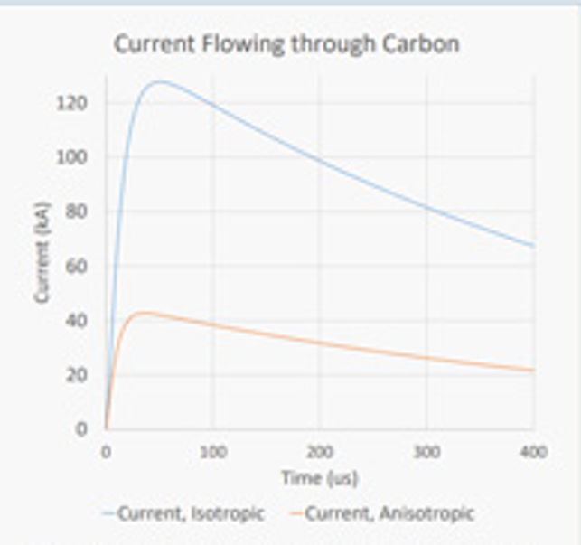
Fig. 1 A plot demonstrating current levels in isotropic and anisotropic carbon cases
Repair is not only expensive but also physically challenging, given the logistical constraints. Lightning Technologies, an NTS company, is a world leader in the design and validation of sophisticated lightning protection systems for the aerospace industry, including aircraft, space vehicles and launch facilities. The company also develops systems for wind turbine farms, industrial complexes, golf courses, theme parks and other high-risk locations.
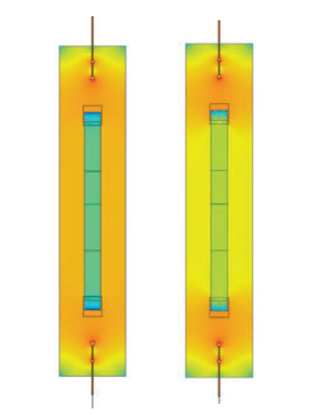
Fig. 2 Simulation results showing the current density on a sample wind turbine blade made of several carbon stacks
Engineers at NTS are actively involved in the committees that form the International Electrotechnical Commission (IEC), which defines the lightning levels and situations that blades must endure. Industry regulations such as IEC 62305 require wind turbine manufacturers to incorporate lightning protection designs into their blades.
For maximum protection, it’s essential to know how much lightning current is likely to flow through a blade following a strike and precisely where it will flow. The problem is that simple assumptions about the behaviour of lightning current often lead to inaccurate conclusions.
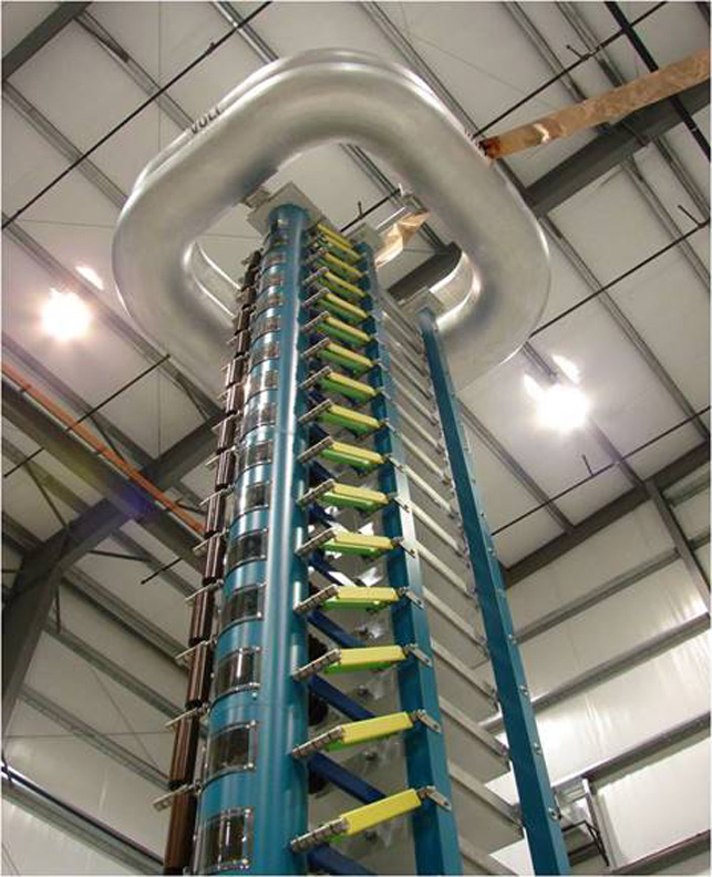
Fig.3 High-voltage 2.4MV Marx generator, operated by NTS
NTS – Deep insights into lightning current
NTS operates one of the most complete lightning simulation laboratories in the world from an 18,000 square foot facility in Pittsfield, Massachusetts. This features 14-and 25-foot tall lightning generators capable of generating as much as 2.4 megavolts (MV).
NTS has been involved in the research and development of protection designs for wind turbine blades for decades.
Because wind turbine blades are airfoils, the company’s deep knowledge base of aerospace applications is directly transferable.
Justin McKennon, who leads the Modeling and Analytical Team at NTS Pittsfield, says that traditional wind turbine protection schemes consist of a surface protection layer (SPL) that covers the lightweight, high-strength carbon fibre composite blades. Often, the SPL consists of a conductive mesh meant to safely carry lightning current from the point where it hit – or ‘attached to’ – the blade and then from the root to the ground.
“Many blade architectures feature stacked carbon fibre structural layers running parallel to the SPL, with periodic electrical connections between the stack and the SPL, all along the blade’s length,” McKennon explains. “This is done to prevent a high-voltage potential from developing between the two, because if that should happen, arcing could occur and damage the blade.
However, while these electrical connections can reduce voltage, they also allow current to flow in the carbon, which creates additional design considerations.”
Understanding a carbon stack’s ability to carry various amounts of current, along with other factors such as likely attachment points and puncture possibilities, is not a trivial task. McKennon says that given the cost to physically test these blades, some of which are 70 metres long or more, the numerical modeling of lightning effects has become a crucial part of the design process.
“Because of the complexity of the physics involved, though, it’s easy to make improper assumptions that can have a large effect on the accuracy of the models,” he adds.
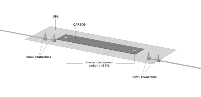
Fig. 4 Geometry of the thin aluminum surface protection layer (SPL) placed on top of a carbon stack
Simulation reduces overengineering
One common but incorrect assumption is to assume that the carbon stack’s conductivity is the same in all directions, even though in reality, there could be significant differences in carbon’s conductivity along different directions.
Figure 4 on the next page shows the geometry of a carbon stack placed 5 millimetres below a 500-metre thick SPL mesh made from an aluminium sheet, the conductivity of which is set according to experimental measurements. The carbon’s conductivity is also set according to experimental values, and both its idealised isotropic and realistic anisotropic behaviour have been considered in the Comsol model.
An analytical representation of an IEC-standard current waveform is used to inject current into one end of the SPL. The current exits at the opposite end through a down conductor, which is made of copper, as are all of the connections to the carbon.
To investigate his designs and model the propagation of electromagnetic pulses, McKennon solved a timedomain wave equation for the magnetic vector potential in Comsol’s Multiphysics software. The results enabled him to determine the associated currents, electric fields and other values at those points, providing insight into the current’s overall behaviour throughout the entire structure.
The isotropic case underestimates the amount of current travelling through the SPL, implying that more current is travelling in the carbon and not in the SPL (Figure 5).
Carbon is made up of many layers of individual fibres. It is very conductive in the fibre direction, but getting current into and out of the carbon is very challenging.
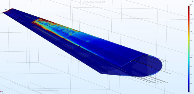
Fig. 5 Simulation results, showing that the amount of current in the idealised isotropic case is significantly less than in the realistic anisotropic case
If too much current has to pass through an interface between the carbon and something else, many of the individual fibres in the carbon can be burned away through heating and/or arcing (Figure 2). Carbon bears the primary structural loads, and damage here greatly reduces the lifetime of the blade.In some cases, it can lead to catastrophic loss of the blade – so more current in the carbon is something engineers seriously want to avoid.
The isotropic case grossly overestimates the amount of current in the carbon, because it ignores the very real orientation-dependent resistances in the material (Figure 1). Thus, given its large volume and comparable length, the carbon seems to be a more preferred current path than the SPL, even though in reality, that isn’t the case. Making such an overestimate might introduce additional challenges that are not present, thus slowing down the development process and leading to an over-engineered product.
McKennon says, “In modelling such complex physics, you really have to know what’s important and what’s just noise, and you must build your model carefully in a stepby-step fashion, so that no errors or false assumptions are introduced that can significantly affect your results.”
“Our ability to rapidly simulate and turn around models greatly reduces programme risk and allows for engineeringlevel data to be obtained almost in an on-demand fashion,” says McKennon. Rather than spending time and money on fabricating complex test articles, he explains, the team uses Comsol to simulate physical phenomena and drastically reduce the ‘problem scope’ for projects. In many cases, critical data simply cannot be measured on real test articles. Simulation and analysis plugs this gap.
“Time is money in our industry, and our customers are very pleased with the service we’re able to provide, thanks to these capabilities. In fact, some customers are so confident in the validity of our simulations that they’ve begun to make wholesale business decisions based solely on our results, with little experimental verification. With so much at stake, we simply can’t afford to make mistakes and Comsol is a valuable tool that we trust to deliver real-world accuracy.”


