

Vero is one of a rare breed of 3D technology vendors that focuses on one thing. Getting specific jobs done. Whilst other better known vendors develop generic tools that serve a huge, but highly horizontal slice of the 3D market, companies like Vero master the verticals and then expand outward.
Vero’s background is in preparation for manufacturing, whether that’s 3D design and simulation – the focus of this article – or mould and die design and NC programming which we’ll cover in the next edition of DEVELOP3D. The company develops a huge range of tools that support tooling design, machining, progressive die development, 3-axis up to 5-axis machining and all points in between.
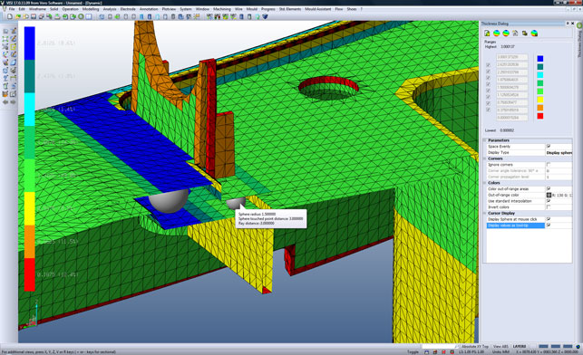
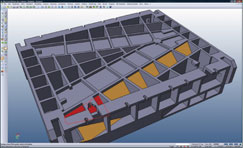
Part thickness showing rolling ball results
In recent years, Vero has redeveloped its range of systems to integrate new technology (such as VISI Flow for injection moulding simulation) and to bring its software up to speed. Today, VISI is a fresh and modern looking system that has some serious power beneath a very shiny exterior. So let’s have a look at what’s new.
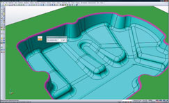
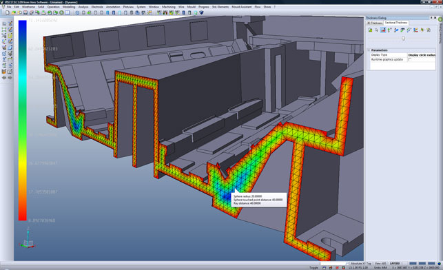
Part thickness displayed with ray method
User experience
VISI’s User Interface (UI) is under a constant state of refinement and many of the commands have been consolidated in recent releases, particularly in the machining arena. For the 17.0 release, the emphasis is now on making the 3D graphics work faster. By working with ATI and Nvidia, Vero has implemented a new technology called Vertex Object Buffers (VBOs), which can help boost real-time 3D performance. VBOs take raw geometry processing away from the CPU and move it onto the GPU (Graphics Processing Unit). As all data is loaded up to the GPU, the amount of memory on the graphics card is important. Any professional OpenGL 2.1+ card with 256MB or more should be enough, but check with Vero for advice. If you don’t have enough graphics memory, the performance will slow down considerably.
While we haven’t tested the technology first hand, Vero claims that by implementing VBOs, combined with other graphical developments, it has managed to increase the frames-per-second rate by over 20 times. This should not only make on-screen model rotation smoother but should enable users to work effectively with much more complex geometry sets, which are typical of Vero customers.

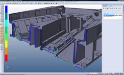
Dynamic sectioning of results
Part development
Moving onto the use of the system ‘in anger’, the first development of note is the work on geometry alignment or mating. This refers to both 2D and 3D geometry and allows users to quickly grab geometry, copy it, paste it and reuse it. In relation to tooling design, either in the form of the tools themselves or plastic components (such as bosses, snap fits and such), the ability to quickly grab geometry, wrangle it into position and continue to work on it is invaluable, but repetitive, so this makes huge sense.
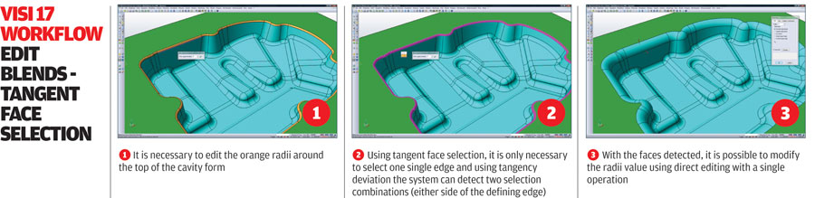
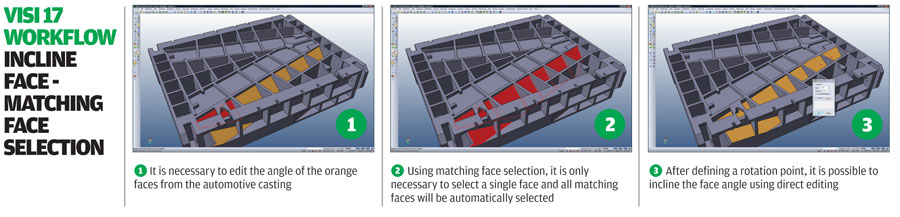
Another generally applicable update is the face selection tools. When selecting a face, the system can now find matching faces by cylindrical or planar relationships. This is great for moving hole features or pocket faces within a complex solid. The face selection can even find tangentially connected faces within a user-defined angular deviation based on seed face or edge pick. With VISI’s surface modelling tools, users can make some pretty serious modifications using direct modelling tools – and it’s been able to do it for years – how about that for synchronous technology?
Click here for an exclusive Visi17 workflow guide – Editing tangent face selection
Assembly modelling
In previous releases, when working on assemblies, users would need to run basic volume calculations and then hand calc the weight. This release gives ready access to much more information about how a part stacks. Alongside auto-calculated volume, users can now define a material from an extensive database, as well as cost, and supplier, for example. This pays dividends when creating Bills of Materials, or running up cost lists. On a design level, centres of gravity can also be accurately identified. This is essential for tooling and positioning the eye-bolt for lifting mould stacks.
Thickness analysis
Another incredibly handy update is the introduction of model thickness analysis, something that’s been spun off and extended from Vero’s VISI Flow product. Basically, this allows users to discover a part’s true thickness, which is essential for ensuring good mould-ability. Any major change in part thickness can cause major moulding issues such internal voids, surface sink marks, unpredictable shrink rates and ultimately, longer cycle times. The system uses two algorithms – a ray-based method that is common in many CAD tools, but also a rolling ball approach.
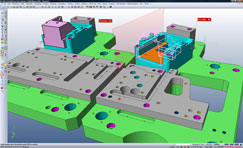
Intelligent mating conditions for solid and wire geometry allow quick and easy geometry reuse, whether 2D profiles or 3D geometry
The shooting ray method fires a ray through the model along the surface normal until it hits a second face. The disadvantage of this approach is that it doesn’t give a true 3D thickness as it is only looking in one direction.
The rolling ball method is based on the largest sphere that can be placed within the model without intersecting any other face.
Whichever method is used, the system presents the results with a customisable range shading, together with sectioning tools, which are handy for finding internal areas which could cause sink marks. The results can then be saved out as HTML files and distributed.
Drawing and plotting
Moving onto the heady world of drawing creation, there has been a lot of work for this release, particularly in regards to assisting with the creation of general assembly layouts from a fully complete stack. One major enhancement in this area is the ability to split the VISI file into separate 3D & 2D environments to allow multiple users to work on product detailing.
Once completed, the individual files can be brought back together into one file and the links to the original 3D data rebuilt. This is backed up with view creation, which is much more automated, and creates plate layouts, and sub-assembly diagrams of each individual component and then automatically scales to fit the selected paper size. It doesn’t add the annotation, but the system creates the basic page layouts automatically saving users the repetitive work often involved.
Click here for an exclusive Visi17 workflow guide – Face selection
Plotting is something that seems somewhat trivial to discuss these days, but it’s still incredibly important for many. This release allows users to preview prints and see exactly what they are going to get. Page size is set according to printer and distributed accordingly. For example, A4 prints go to the standard office printer, while the big sheets go to wide format printers.
Conclusion
In the scope of this review, we’ve barely scratched the surface of what VISI is capable of, and we’ll move onto the more specialised tools next issue when we look at injection moulding simulation, mould design and machining. For now, suffice to say that VISI has an incredible quantity of tools for adapting and fixing imported geometry, for modelling from scratch, or for making modifications for pre-manufacturing preparation. And while these tools have been within VISI for nearly two decades, the developers are doing sterling work to ensure that they are up to date, modern and fresh. I can’t wait to dig into the manufacturing-specific tools in our February 2010 edition, so stay tuned for more.
| Product | VISI 17 |
|---|---|
| Company name | www.vero-software.comVero Software |
| Price | On application |


