

Machine design is a complex process. The interaction between the mechanical design, electrical design and the control software can give many organisations serious headaches.
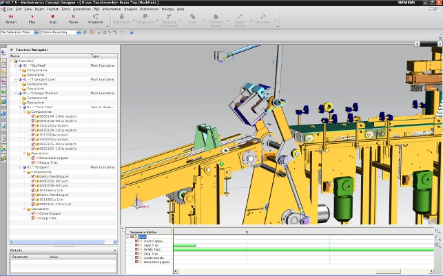
Braas Machine: the sequence editor, which runs along the bottom of the screen, enables the timed functions of a machine’s operation to be planned out
In many cases the electrical and software development can’t begin until the mechanical design is near complete.
The problem is the majority of design methodologies for electromechanical products are serial, and the teams involved have less than optimum interaction prior to machine integration.
There are many digital tools to carry out the individual portions of a machine’s development – mechanical, electrical, schematics and PLC software – but it has not been possible to consolidate these disciplines into a single functioning digital prototype.
This makes it difficult to test concepts and evaluate alternatives. It also means delays are common as initial build becomes a constant round of adjustment, retest and debugging.
Against this backdrop comes Siemens PLM Software with its brand new Mechatronics Concept Designer (MCD). The genesis of the system is the relationship between Siemens PLM Software (Solid Edge, NX et al) and the Siemens many of us know – the provider of automation and control systems.
The software has been built on a desire to provide a more efficient evaluation, design, manufacturing and test environment for its customers and is aiming to slot itself into the typical machine design workflow.
At present, there is a bottleneck between the stages of gathering customer requirements and starting the detailed engineering – typically the point where things are most fluid but also most critical.
For many larger companies there is little direct linkage between requirements, product development assembly and test. Requirements documents are often spreadsheet or text based and moving from requirements to function and form is an exercise that often bypasses prior art. This makes it difficult to ensure all requirements have been met until final build and test.
This bottleneck represents a serious headache for many of Siemens’ customers as firm geometric concepts are required before stages such as motion control software and electrical design can begin.
After all, to define how motion controls function is difficult without known dimensions. Unfortunately, today’s heavy CAD overhead means that the key geometry is difficult to plan out at this conceptual level.
So let’s see how Siemens’s offering fits into a typical workflow.
Functional structure
Sophisticated machinery, just like cars, planes and high tech products, has increasing software and electrical/electronic content, making the design and development process more complex.
With this in mind, the machinery sector is increasingly looking to adopt principles from these other industries to design and deliver better product development strategies.
The V-model is recognised by many as the most practical methodology to deliver improved product and processes.
As a systems development model, it is designed to simplify the understanding of the complexity associated with developing systems. In systems engineering it is used to define a uniform procedure for product or project development.
Following system specification, the norm is to define a product’s functional nature. This commonly takes the form of a hierarchical list and defines exactly what functions the machine should perform and how. It’s typically componentised by sub-systems and each has its own set of functions.
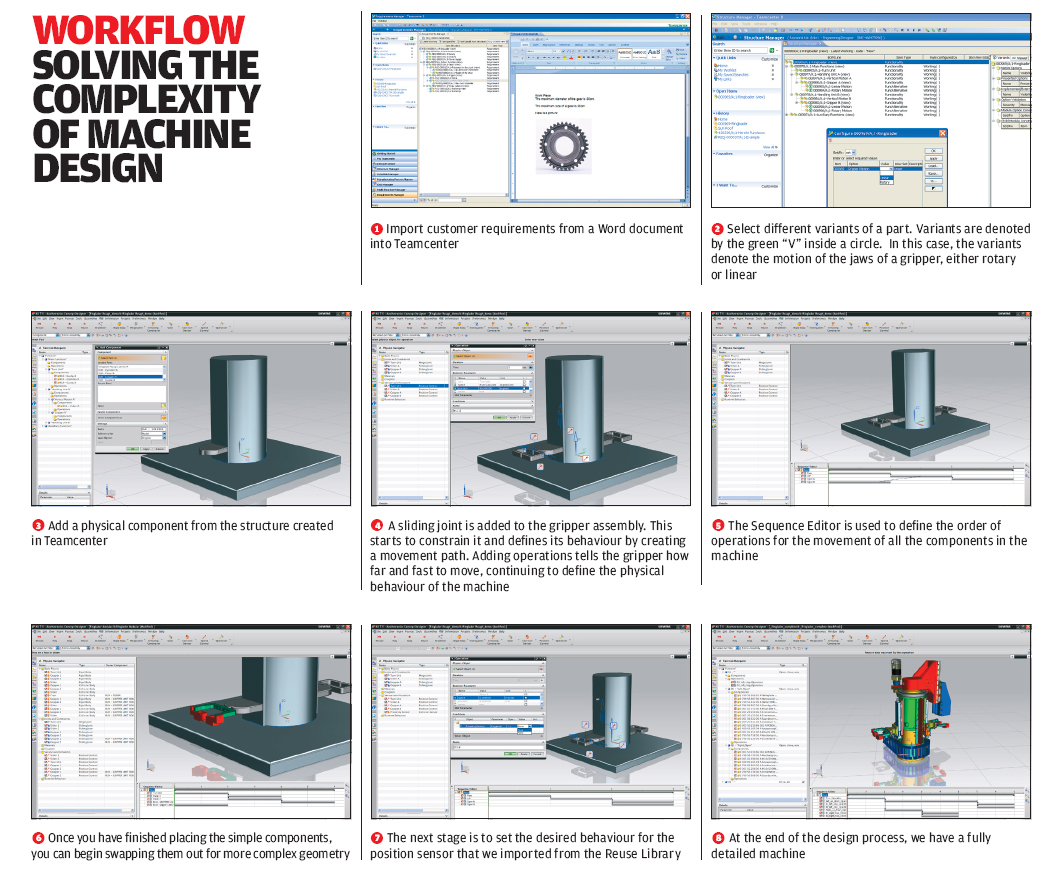
If you’re using Teamcenter to manage customer requirements, these can be quickly extracted and organised into the required list. The system will maintain the links from the Functional Structure back to the Requirements, so should changes occur, they can quickly be identified and taken care of.
It should be noted that requirements aren’t necessarily numerical in nature (often being textual) and they can’t currently be linked directly to input parameters.
If your organisation isn’t using Teamcenter, it’s a manual process to create the Functional Structure to form a solid concept of how the machine is going to function. The next step is to flesh that out with basic geometry.
Basic geometry and functionality
The starting point is a basic 3D model that describes the form of the machine in simple terms. The good news is that MCD has a comprehensive set of easy-to-use geometry modelling tools as it’s built on top of Siemens PLM’s NX 7.5 system.
The next step is to define the movement relationship between the various blocks, whether that’s sliding or rotational joints.
This functional model has a direct relationship to the form and function of the final product. You can re-use functional components that have been used before (see our section on data reuse). Other than that the mechanical, software and electrical elements are developed to deliver the functions defined in the functional model.
You can simulate the concept model at any point in the process before physical/software/electrical design stages. This is pretty common in the electronic and software world, less so in mechanical, but the emergence of cross-domain modellers (i.e. Modelica) show the direction that the industry is going.
To help perceive how this influences the complete design, these could also be considered to be the basics for the electrical design. Once these two core components are in place, you then add the functional properties for each joint such as movement limits, speed etc – again, this is best seen as the basic starting point for the motion control design.
Once all of this is complete, you have the basics of the machine in place – the geometric form of the machine and the movement/limits of the machines parts.
To add more intelligence and to scheme out how the machine will function, two further tools are used. Firstly, sensors are added into the model which can be used to drive other functions or to drive choices in the software and electrical controls that you’re developing.
For example, limit switches to detect contact conditions and proximity sensors to detect passing objects. The second tool is the Sequence Editor. This is where the timed function of the machine’s operation is planned out using a timeline-based approach to define when specific actions take place.
The integration of the two – sensors that invoke event-based actions dynamically combined with the time-based actions – allows the creation of realistic machine operating environments.
Adding detail & intelligence
Now the system has a good idea of how the machine is going to operate, all manner of information can be extracted from it to further add detail to the model.
For example, MCD uses the PhysX realtime physics engine (licensed from hardware manufacturer Nvidia). This not only allows a realistic simulation of how the machine will operate, but also enables you to extract physical information such as basic forces and dimensions for actuators and drive components.
If Siemens is already a supplier of your parts, then this can bring additional benefits. Combined with NX Motion, the motion simulation application, the output (such as torque and speed curve) can be fed into Siemens’ Sizer system to assist with selecting drive and controls systems.
To close the loop, once the correct components have been found, Sizer can output an .MDEX file which can be read back into Mechatronics Concept Designer to automatically create the geometry of the components.
Now that a good idea of the basics of the system is in place, it’s time to start fleshing out the detailed design – at which the system excels. Due to the tight integration with NX 7.5, core component sets can be transferred to NX and detailed engineering work conducted.
All of the intelligence that you’ve already defined is retained and transferred, so assembly structure and relationships are maintained.
In terms of working with software design, the Sequence Editor is the enabler. From here, it’s possible to export the Sequence of Operation in PLCopen XML-based format. This is a standardised format from the AutomationML group and is supported by a variety of other vendors.
As the software development progresses, it can be connected back into the system and a full simulation of the machine’s functions can be performed. If you’re using external code to control the various machine components and functions, these too can be integrated into the simulation.
The gateway for this is using public calls with software DLLs and, according to Siemens, it’s a relatively straightforward process to connect them up.
Reuse of data
Alongside the ability to connect previously disparate and isolated components of the machine design process, one of the major benefits of MCD is the ability to reuse data.
As soon as the first project is complete, the information and intelligence you’ve built into the various constituent sub-systems can be reused. They contain not only the geometry of the part, but also the full suite of mechatronics data.
All of this can easily be reused when similar actions or functions are required in subsequent projects. When more projects have been completed, this library of previously defined data can be more readily reused and adapted to the new application, which can potentially save a great deal of time and effort.
Conclusion
While certainly not unique to machine design, the fact is that a heady mix of mechanical design, electrical design and software development can cause serious bottlenecks and workflow issues if treated in isolation.
Waiting until the mechanical design is near complete before commencing other stages doesn’t cut it as the industry strives for shorter development periods. Something else is required. What Siemens PLM has developed is a platform that enables all stages of the development process to begin nearly concurrently with solid concepts in place.
Another benefit is that a project can be simulated and evaluated relatively easily at any stage by connecting these tasks together into a common data model. That allows potential problems to be resolved and new solutions propagated to the various teams much earlier.
This is an excellent first release and it looks like one to watch if you’re in the business of creating complex mechatronic products
There’s also the issue of data reuse. By centralising the majority of data pertaining to a project into a managed structure, reuse of mechatronics information is entirely feasible, particularly if your organisation specialises in variants of a range of machines, rather than one-offs. It’s clear that Siemens has great plans for the Mechatronics Concept Designer and is looking to expand its remit outside of machine design once it’s been through a few release cycles.
There will also be tools to allow greater integration of software design into the system to enable a fully functional virtual model to be created, tested and debugged before getting anywhere near the shop
floor. This is an excellent first release and it looks like one to watch if you’re in the business of creating complex mechatronic products.
www.siemens.com/plm
| Product | Mechatronics Concept Designer |
|---|---|
| Company name | Siemens PLM Software |
| Price | on application |


