

Over the years Pro/Engineer has built a solid foundation in the world of high-tech and consumer electronics.
Talk to any of the leading designers or manufacturers and you’ll probably find that they’re using Pro/E. What connects these high-tech organisations and their products is one thing: complexity. The complexity of the external form, in terms of the industrial design, the complexity of the internals, in terms of design for manufacture and assembly, and the complexity of the electronics within.
In order to effectively manage the design of these complex products it is important to bring all of the data together in a 3D environment. This not only helps ensure correct clearances are maintained and
interferences removed, but airflow and heat analyses can also be performed.
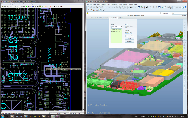
The Electronics integration allows users to work with data displayed alongside PCBA data – fully synchronised so critical components can be found, errors located and design problems fixed
Like the majority of 3D design tools, Pro/E supports the import and reuse of IDF data. This format can be exported from the majority of PCB and electronics design tools from the likes of Mentor Graphics, Zuken, Cadence and Altium. The IDF file takes the form of two files – the board file and the component file – and includes the board profile, the list of components and where those components are positioned on the board.
Collaboration with IDF data works for many users, but the process is not intelligent. It’s best used when there is a single hand off to a client or supplier for work. The PCB gets designed and the enclosure gets built around it.
Increasingly, in a drive to produce better products in a shorter timeframe, electronics and mechanical design changes are happening at the same time. Mechanical design teams build models that reference board geometry and features to accommodate electronics components.
Conversely, electronics design teams reference mechanical features in their board designs. As the IDF file contains the complete PCB, subtle design changes between the two disciplines often can’t be
rationalised and the process breaks down.
With a view to managing incremental changes between mechanical and electronics design teams, PTC has teamed up with Mentor Graphics to create a more intelligent exchange mechanism using a
format called IDX, which is an extension of IDF. There are now tools within Pro/Engineer and PCB and various electronics design software, including Mentor Graphics and Cadence, to enable this workflow, and we’re going to look at how this process works from the perspective of the mechanical designer or engineer using Pro/Engineer.
Mechanical and electronic collaboration
The starting point for collaboration between Pro/Engineer and the PCB design software of choice is the exchange of an IDF file. This provides the complete description of the PCB board at the beginning of the project. From that point onwards whenever design changes are made on both sides, IDX files are exchanged between the two teams.
These IDX files contain incremental updates about where components have changed or moved, if the board has been altered and where – but only that information. For those working in a managed environment such as Windchill, then the information can also be tracked, managed and controlled between the two teams to a much greater extent. But where the process really starts to sing is in the set of comparison and collaboration tools that PTC has built in to support this new workflow.
To validate and compare, users can work through incremental changes, proposed either by the electronics or mechanical design teams, using visualisation methods appropriate for both audiences
While the IDX format provides the mechanism by which design changes are made, the snappily titled Pro/Engineer ECAD-MCAD Collaboration Extension (introduced in Wildfire 4.0) is what enables the Pro/Engineer user to make sense of changes from the electronics team. This could be to suggest new positions for movement of components or to highlight potential problems, such as clashes, interferences and misalignments.
There’s also a raft of tools for viewing this information and a lightweight view of the PCB layout can be linked to the 3D rich Pro/Engineer model, so the impact of design changes can be assessed. If a part is selected in the PCB view it is highlighted in the Pro/E view and vice versa.
There are also some view and mark-up tools that allow the Pro/E user to document the suggestions then pass this information back to the electronics team.
The electronics team imports the IDX file into their tool of choice, loads up any edits that have been made in Pro/Engineer and rationalises them against their can again pushed back to the mechanical
designer as an IDX file.
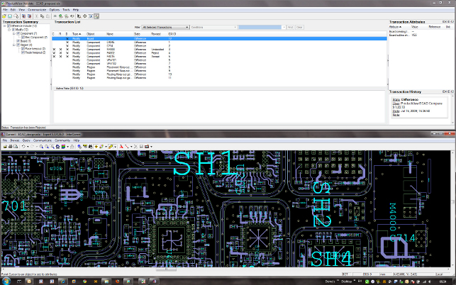
To help the Pro/E User view and rationalise any changes, PTC’s ProductView ECAD Compare tool can be used to identify exactly what’s changed between the baseline data and the resultant model.
It lists changes and differences in parts, position, size, rotation, board, keep in/out areas to a very granular level. Changes are then accepted or rejected (in a similar way to how changes are tracked in a Word document) and the process continues in an iterative way.
To progress to a final design, a stream of data is typically swapped between the mechanical and electronics teams and the ProductView ECAD Compare tool helps ensure that both are working with same data.
Conclusion
Complex design breeds complex processes and as we move further into geographically dispersed supply chains, the interaction between disparate teams can wreak havoc with workflow. The constant ‘battle’ between mechanical design and electronics development is a problem that many organisations face and PTC’s offering can help alleviate a lot of the issues that arise.
By moving away from an IDF-based workflow that takes an all or nothing approach to data to a process that is more granular and incremental, there’s huge potential to foster collaboration, remove barriers and improve productivity. PTC’s IDX-based workflow provides an environment where problems can be discussed and the change process can be managed in a more efficient manner.
This gives manufacturers of high-tech and consumer electronics a much better chance of creating an optimum product in a shorter cycle and that’s worth its weight in gold.
Finally, it’s also interesting to note that the IDX format has been ratified by the ProSTEP organisation under its standards-based name, EDMD, so the format and the processes are fully documented. At the moment, it’s PTC and Mentor Graphics leading the charge, but we hope to see other IDX-based solutions come to market soon.
www.ptc.com
Pro/Engineer Spark Analysis Extension (SAX) Module
Developed in conjunction with a large, global high tech & electronics customer for the Pro/Engineer Wildfire 4.0 release and made publicly available to the masses with the Wildfire 5.0 release, the Pro/Engineer Spark Analysis Extension (or SAX for short) includes both creepage and clearance analysis for electronic or electrical components.
Essentially this is a set of specialised tools that uses electrical simulation to find where sparks can travel between electrically charged components, either along the surface of the product (creepage) or through the air (clearance). Where most 3D design systems are geared towards finding collisions and interferences, this tackles something a lot more complex as the system is looking for the minimum distance between two points, either through the air or along the surface of the part.
The use of the software is pretty straightforward. The first step is to define the relative neutral/ground, positive and negative values for the components and then assign those values to each part or sub-assembly. There are selection tools that make finding conductive parts easy. The system then performs the simulation and presents the results. Selecting each result highlights the geometry and the shortest distance as a coloured line. The system provides control over both the minimum distance and an additional threshold, so users can override close values (but an override with a comment for check in needs to added for traceability).
What’s interesting is that this simulation and its results are stored as part of the model tree, so any design changes made can be quickly rerun through the system for further validation. It also gives great potential when it comes to using the Behavioural Modelling Extension (commonly referred to as BMX) tools in Pro/Engineer for design optimisation work.
| Product | Pro/Engineer MCAD-ECAD Integration |
|---|---|
| Company name | PTC |
| Price | on application |


