

In April’s article, we examined direct stress and shear stress – the two types of stress that exist when we consider stresses in a Cartesian coordinate system. We recognised that the notion of shear was necessary in order to allow the all-important direct stresses to act at any given angle (and not just parallel to the X, Y or Z directions). We will take this idea further when we look at principal
stresses so beware!
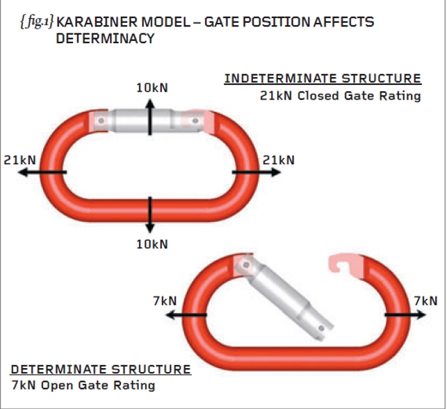
This month we will perform hand calculations and Finite Element Analysis (FEA) on a classic karabiner. The karabiner is used by climbers as a rope-joining mechanism – see {fig.1}. With the gate closed, the karabiner is rated at 21kN end-to-end and 10kN acrossgate. With the gate open (not to be recommended!) the end-to-end rating drops to 7kN.
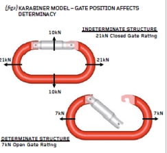
Fig.1
The first thing to recognise with the karabiner closedgate is that the load path is not unique. In other words, when we apply an end load to this device, some of the load will travel through the forged aluminium “C” section and some of the load will pass through the gate. We could estimate that the load split is 50/50 but we don’t know – a plastic gate for instance may attract much less load than
50%. Thus, with the gate in the closed position, we have what is termed an “INDETERMINATE” structure (so-called because we can’t readily determine where the load will go).
When the gate is open we now have a unique load path through the main forged “C” section and the structure becomes “DETERMINATE” (we can determine where the load will go). In our everyday engineering we should be aware of the issue of determinacy – determinate structures can be addressed with hand calculations while indeterminate structures generally can’t. Indeterminate structures may be much more susceptible to manufacturing limits and fits but we’ll leave it there for now.
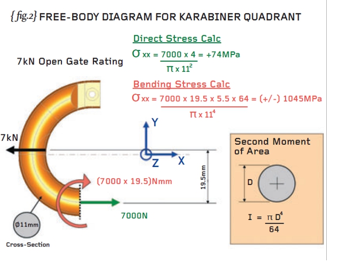
{fig.2} shows the karabiner with the gate removed (so that we can perform hand calculations on the determinate “C” section). Given that we would like to calculate the stresses along the straight portion of the “C” section then a cut has been made in order that free-body analysis can determine the internal forces at the cut.
It can be seen that the quadrant is in force and moment equilibrium when a direct force of 7,000N and a bending moment of (7,000 x 19.5) Nmm is applied to the cut section. This free-body diagram instructs us to carry out a direct stress calculation (carried out in green text) and a bending moment calculation (carried out in red text).
The bending stress (at +/- 1045MPa) is far greater than the direct stress (at +74MPa) and we should watch out for bending as a major source of stress from now on. BEWARE!
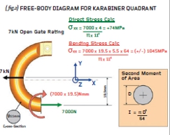
Fig.2
While the aforementioned direct stress calculation was very straightforward (force/area) the bending moment calculation was slightly more involved and we should now examine what was done in that regard. The bending stress induced when (say) a bar of steel is subjected to a bending moment, M, is not a straightforward function of the area of the bar.
The bending stress is proportional to the moment, M, the distance from the centre, y, and the second moment of area, I. Dealing with y first then this is the linear distance from the centroid of the section (the centre-of-gravity if you made a plywood replica of your section) to the point where you want to determine the stress (usually the top or bottom of the section).
The second moment of area is derived by considering the section as an infinite number of thin “leaves” (like the core of a transformer) and calculating the area of each “leaf” and multiplying that by the offset distance squared. In other words, the first moment of area is area x distance and the second moment of area is the area x distance x distance (area x distance-squared). For a rectangle (breadth, b x depth, d) the second moment of area is bd3/12 and that for a solid circle is ðD4/64. Check the bending stress calculation on {fig.2}.
Staying with {fig.2} we should be able to appreciate that the direct stress and the bending stress are defined in the same direction (parallel to the global X direction).
This allows us to add the two stresses together giving a resultant stress at the inside of the “C” as 1,119MPa (tension) and a resultant stress of minus 971MPa (compression) at the outside. Check that you agree.
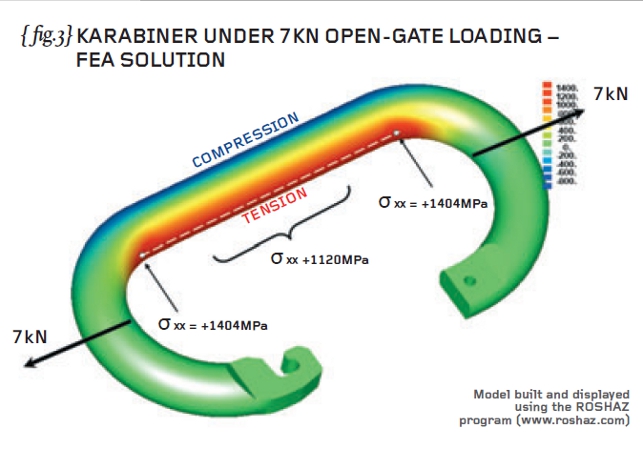
Finally I have carried out Finite Element Analysis of the open gate karabiner (subject to 7kN loading) and the predicted stresses away from the end of the radius (1,120MPa) show excellent agreement with our hand calculations (see { fig.3}). What is happening where the straight part of the “C” joins the curved part of the “C”?

Fig.3
We have demonstrated the danger of bending – as soon as you see two forces incorporating an offset (see {fig.2}) then you know that you have a bending problem. Always re-check your calculations to see that you haven’t forgotten a bending problem. More next time…
R P Johnson BSc MSc NRA MIMechE CEng – Technical Director, DAMT Limited
Stress analysis of karabiner carried out using the ROSHAZ program.

Part four of an engineering master class, this month: Bending Stresses


