No doubt many readers have had a go at paint-balling. For those that haven’t then the aim of the game is to shoot a paint-filled spherical capsule (approximately 20mm in diameter) through an air-powered rifle.
The capsule breaks leaving a tell-tale ‘hit’ (on the tender part of the thigh if your aim is good). The guns use compressed gas (usually air) to propel the paint ball with speeds approaching 300 feet-per-second.
They do hurt! The aim of this study is to assess the stresses in the propellant vessel and check that these do not exceed the allowable of (say) 200MPa.
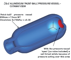
The basic dimensions of the propellant vessel are 90mm diameter by 7.5mm wall thickness and 240mm long (see {fig.1}).
The internal pressure is 250bar, and given that we’re going to be working in modified S.I. units, then the pressure converts to 25MPa (or N/mm2).
Note that we will represent the vessel without the valve and there is therefore a net thrust acting on the red area depicted in {fig.1}.
The first thing we should do is perform some hand calculations – these will give us confidence in our FEA results later on and will force us to think about some engineering!
In the case of a thin pressure vessel such as this, the hoop (circumferential) stress is given by pr/t and the axial stress by pr/2t (where p is the internal pressure, r is the mean radius and t is the thickness of the vessel).
These hand calculations render 138MPa and 69MPa for the hoop and axial stresses respectively. Check me on these.
In the centre region of the vessel (away from the hemispherical ends) these stresses will occur without shear and thus are principal values.
The second thing we should do is make a ‘Simple’ Finite Element model. I stress the word ‘simple’ because no doubt you have some lovely 3D CAD data and you’re itching to make a really sexy-looking solid model.
Don’t be tempted – instead we’re going to utilise the fact that any radial slice through the vessel will be identical to the next. Given that the internal pressure loading shows the same symmetry then we can rightly choose to build an axi-symmetric model.
Most FEA packages will be able to perform such an analysis – it is the most efficient way of solving this particular problem.
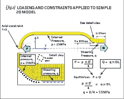
{fig.2} shows the geometry of the model in the XY plane with all points in positive X. (Most FEA systems will require that you build your axi-symmetric model in the XY plane but not all – check your user manual).
The geometry can be obtained from a slice through the 3D CAD data or can be built from scratch using drawings or measurements from an actual vessel.
To convert the ‘empty’ geometry into a working FEA model, we need to fi ll the region of interest with a mesh of finite elements.
In this case I have filled the aluminium wall of the vessel with 8-noded axi-symmetric elements (see the detail view of the mesh on {fig.2}), which look like fl at 2D patches but the FEA system understands them as rings that extend for all theta.
The properly connected mesh and the application of material properties (minimum being Young’s Modulus and Poisson’s ratio) gives the computer model a description of the stiffness of the vessel.
Now we must apply some sensible loading to our model: if you refer to {fig.2} you will see that I’ve described a pressure thrust load (‘F’ acting on the red patch) and a thread-shearing thrust load (‘Q’ acting where the threads would be).
Both these are straightforward loads in Newtons. The force F is induced by the internal pressure acting on the red patch on the inside of the vessel (pressure x area) and the force Q is induced by shearing of the threads (shear stress x threaded-portion area).
For equilibrium (the vessel does not fi re across the battlefield when pressurised) we write F=Q and this allows us to calculate the shearing stress (traction pressure) on the threaded region of the neck (7.5MPa as shown in {fig.2}).
At this stage therefore we have a good mesh with natural pressures applied such that there is no net thrust in the axial direction. You will need to check the load balance yourself – it won’t be exactly zero but it should be small in comparison to the thrust forces F and Q (mine was 0.095 N of imbalance).
We must now constrain the model from rigid body movement otherwise the slight imbalance will cause the model to drift away up/down the Y axis.
The correct thing to do here is to constrain ONE node in the axial direction – any ONE node is correct and all other support scenarios are wrong! [Note that we don’t need a constraint in the radial (X) direction because the elements are eff ectively ‘hoops’ and therefore have stiffness in the radial direction].
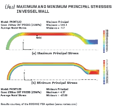
The model will run in seconds and you will be able to present principal stress contour plots like mine (see {fig.3}).
The maximum (most tensile) principal stresses in the wall show good agreement with the hand calculations and we should be able to deduce that the minimum principal is (mostly) radial and equal to zero on the outside and -25MPa (or thereabouts) on the inside of the vessel.
Think we’ll add some threads and a valve next time.
R P Johnson BSc, MSc, NRA, MIMechE, CEng – technical director, DAMT Limited

Part eight of an engineering masterclass. This month: ‘Paint-Ball ‘ Pressure Vessel


