In previous articles we have shown that direct stresses are the key to understanding basic stress analysis. We have shown that only three direct stresses exist in reality – these can be tension or compression but can occur at any angular orientation (all three are mutually perpendicular to each other) – we have defined these as our principal stresses. They are the natural stresses flowing around our component as dictated by the loading and the shape/stiffness of the piece under consideration.
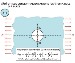
{ fig.1} shows a circular hole in an infinite plate (or at least a relatively small hole in the middle of a large plate!). The left and right-hand edges are subjected to a tensile pressure/stress denoted by “ó” while the top and bottom edges (and the inside of the hole) remain stress-free.
The plate therefore is under uni-axial tension in the horizontal direction. The exact solution to this problem was solved by the German Engineer, Ernst Gustav Kirsch (1841-1901), and part of that solution, the circumferential stress variation, is added to { fig.1}.
From our basic understanding of stress we should know that the radial component of stress is zero at the edge of the hole and it shouldn’t surprise us either that the highest values of circumferential stress occur at the edge of the hole as well. The Kirsch stress distributions reduce to a factor of three-times at 12 o’clock and 6 o’clock, and minus-onetimes at 3 o’clock and 9 o’clock.
[For homework evaluate the given expression at the edge of the hole (r=a) and for theta = 0 and 90-degrees. You should agree with the 3 and -1 quoted above].
The quoted solution { fig.1} means that when a plate is loaded in one direction with a tensile stress of 150MPa then the peak tension is 450MPa (acting parallel to the applied stress) and the peak compression is -150MPa (acting in a direction perpendicular to the applied stress). Both these stresses act in the circumferential direction and are principal values.
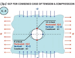
{ fig.2} shows a further complication to the problem where compression has now been added in the vertical direction. Our instinct should tell us that the ovalisation of the hole introduced by tension must be made worse by the compression acting at 90-degrees.
Let us investigate further: if we consider only elastic stresses then we can consider the effect of tension and compression separately and then ADD the two effects together. This is the principal of superposition – we can superimpose one set of results onto that of another because the problem is linear (the displacement (and stress) is proportional to the applied load).
{ fig.2} shows that you have three and minus-one acting for the tension field and three and minus-one acting for the negative compression field. The net effect is that the stress at the top and bottom of the hole is tensile and equal to four-times the background stress and that the stress at either side is compressive and equal to minus-four-times the background stress (4, -4).
We have therefore developed a useful observation; when a circular hole is subjected to a single direct stress then the stress concentration factors are three and minusone; when the hole is subjected to equal tension and compression then the stress concentration factors rise to four and minus-four. The first case is uni-axial tension and the second case is pure shear! We therefore see that pure shear (tension and compression in principal planes) is more searching than straight tension or compression (and we saw something similar to this in the last article).
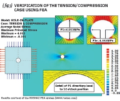
{ fig.3} shows the verification of the combined tension/compression problem. A plate of dimensions 200mm x 200mm (unit thickness) has a hole of 10mm diameter drilled through the centre.
The edges are loaded with a unit stress in tension and compression (+1MPa and -1MPa). The peak P1 stress (most tensile principal value) is seen to occur at the top and the bottom of the hole where it is equal to 4.05MPa.
If we toggle to the P3 stress (in order to search for the worst compressive stress at any angle) then we see that the P3 stress is most compressive at 3 o’clock and 9 o’clock and the stress at these locations is minus 4.05MPa. The exact solution is four and minus-four so the FEA results are within 2% (not too bad considering that we haven’t modelled an infinite plate).
In conclusion we can see that if we disturb a stress field by a hole (or any other feature such as a notch or a groove) then the stresses local to that feature are raised. Although the stress is highly localised, the effects can be significant, perhaps greatly reducing the fatigue life of the component under consideration. We should take these stress-raising effects into account when carry out
our detailed design work.
Make sure you complete the aforementioned homework before we move onto Finite Element Analysis proper next time…

Part seven of an engineering master class, this month: Stress Concentration Factors


