There is one, often over used, 3D design feature that can have a huge knock on effect on Design for Manufacture. John Tumelty asks that we think before we go crazy with the fillet command
The fillet radius is an engineering and design essential, enabling areas of stress concentration to be relieved while also aesthetically improving a component design. When cavities are CNC milled into a mould tool, filleted external part corners are also a necessity for this manufacturing process (you can’t cut a square hole with a round cutter).
With modern 3D CAD packages the process of adding filleted corners is blissfully simple; select faces or edges, click the button and hey presto the whole part can be filleted with ease. This is in contrast to the bad old days of pencil and paper, where adding fillet radii was a laborious process. However, it also resulted in more time and thought being given to what can be a tricky problem.

Figure 1
The simplicity with which corners can be filleted in modern 3D CAD packages has led to some new problems regularly occurring with component design. While the process of applying the desired fillet radii is simple, the thought process and design of said fillets should follow the same care and consideration as the rest of the design process. Below are a couple of examples of problems caused solely by fillets that I see every day.
The orphan fillet
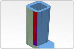
Fillets, in certain geometries, can be a problem. Take, for example, the part shown in Figure 1. The green faces of this part (including the left and far sides that don’t show in the diagram) are created by the one half of a mould and are drafted appropriately. The surfaces shown in blue are created by the other half of the mould and are drafted in the opposite direction, which means they taper towards the top of the diagram. The problem is with the fillet highlighted in red.

Figure 2
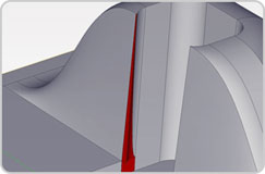
The CAD software, recognising that the fillet connects faces drafted in opposite directions, has tried to resolve the conflict between two opposite draft directions, but has done so unsuccessfully. The reason for this is that, in reality, this fillet cannot be part of either mould half. In other words, this feature is an orphan. To clarify, Figure 2 shows what the mould cavity would look like if this fillet were created by the fixed half of the mould (the green half). There would be a problem in the area that appears in Figure 1 as a small red triangle on the base of the part. The part of the cavity that created the fillet (highlighted in red) would trap the moulded part under it at that triangle when the mould opens.

Figure 3
There are three possible solutions to the problem of the orphan fillet. The part could be redesigned so that everything was drafted toward the top. In that case, the entire part, fillets included, could be moulded in one half of the mould. You could avoid vertical fillets that connect faces drafted in opposite directions. This would prevent the problem in the first place. Or part could be manufactured as designed with the addition of a moving core, but this would significantly increase the tooling cost.
Parting line radII
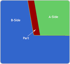
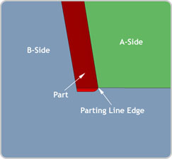
Another area of moulded part design that can suffer as a result of reckless filleting is along the split line of the mould. If you look at Figure 3, you see the parting line where the two mould halves meet to form the sharp edge of the part. In machining and running moulds, there is always some tolerance, but slight movement of the parting line to the left or right will not change the geometry of the edge. In Figure 4, on the other hand, both the mould halves form the parting line edge, so any mismatch in the mould will leave a ledge, changing the shape of the part at the parting line.

Figure 4
Final thoughts
Like every stage of the design process, the finishing touches such as fillets can have a remarkable influence on the manufacturability, performance and aesthetics of the final product. However, just because the software has made the process blissfully simple, the designer doesn’t need to act in the same way.
John Tumelty is managing director of Proto Labs. He is mildly amused whenever someone pronounces fillet as you do when ordering a Fillet O’Fish.

John Tumelty recommends caution when using the fillet tool


