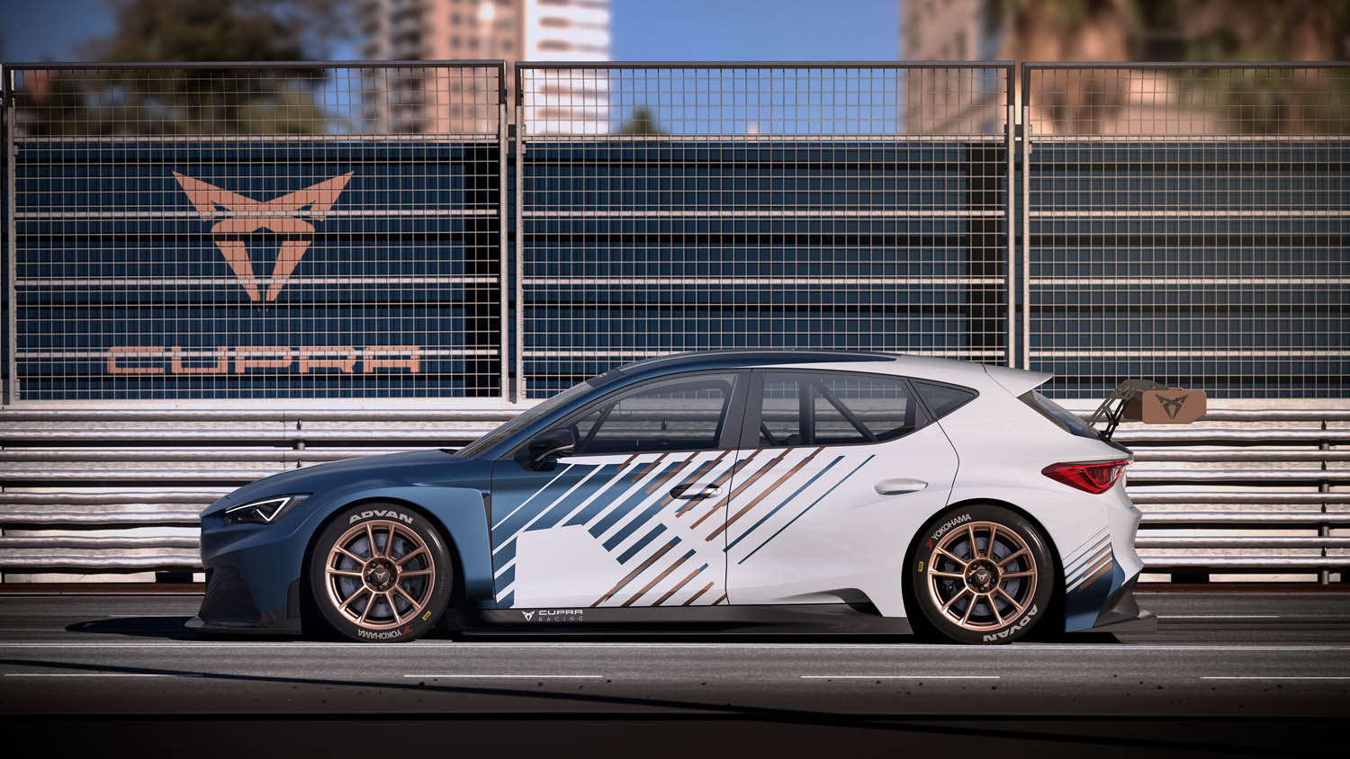
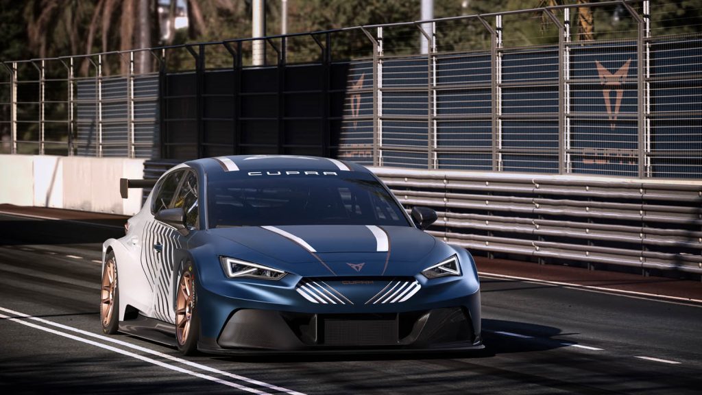
Behind the Cupra Racing insignia is over 20 years of racing experience and a vehicle design team that never stops optimising. We speak to that team about how its design evolution and PTC’s software have matched each other lap for lap
The Cupra Racing livery might be a relative newcomer to racetracks around the world, but the motorsport arm of Seat has a 20-year pedigree, battling it out with rivals in some of the most competitive fields.
In 2021, Cupra took part in over 70 races in world, continental and national TCR series and championships. At the same time, the brand continues its electrification strategy, taking its engineering to new levels with Extreme E and Pure ETCR.
Being competitive on the track requires countless hours of effort and dedication to build a car that’s competitive, with much of that work happening in the early stages of the design of individual vehicle components.
“In the competition world, you have to improve the car you made the previous year,” says head of full vehicle design at Cupra Racing, Jaume Tarroja.
“There is a need for constant improvement with the aim of reducing manufacturing costs.” From its beginnings under the Seat brand, Cupra Racing has relied on PTC for its 3D CAD software, beginning with Pro/Engineer, and evolving to take full advantage of the latest features of Creo to develop components much faster, as well as to test their performance.
“We used to design the components in 2D and then they were sent to be manufactured – with the consequent errors that could occur. Now, we can view the car in 3D, with all the components assembled. In fact, we can visualise the whole car on the computer screen,” says Tarroja.
“We can modify the car without changing its design and within a fully stable environment. This has been a huge step forward for us.”
Tarroja lists the top-down design – a skeleton model for the engineers to define the general structure of the vehicles – as a key area of improvement. Related to this, engineers can design and assemble their components with the knowledge that, if a redesign or variation of the skeleton model takes place, these changes are automatically implemented to all components.
Since the skeleton model includes a kinematic mechanism, engineers can quickly simulate the actual motion of the vehicle to determine any interference or collision between components.
Tarroja says that this, for Cupra, is a fundamental step that saves many errors and hours of design repetitions. When added to tools for FEA analysis, it has helped reduce part development time by around 20%.

In parallel with the use of sheet metal modules in Creo, the Cupra team has also decreased the weight of components, saving around 10% without reducing their mechanical properties.
For elements like piping and cabling, Creo enables the layout of electrical wiring and cooling to be simulated. This has been a big step forward for Cupra; previously, a prototype was modelled and delivered to the supplier, who then replicated it.
Now, the team can simulate the wiring system and piping in Creo, so that when the part is manufactured, everything works well at the first attempt.
The team also benefits from parametric surface and freestyle features; these are used in component design, allowing curved parts to be freely designed using a Sub-D moulding feature to provide a higher surface control and finer details, without changing the existing shape.
In the future, this is lending itself to other modules in Creo that Cupra is looking to implement, such as generative design for additive manufacturing and behavioural modelling.
The faster the parts can be on the car, the faster they can be tested – helping its driver stay competitive, no matter the race series in which they’re competing.


