Solid Edge has been through something of a renaissance over the last few years, at least in the interest it’s generated in the design software community.
Never before, or at least for a good decade, has the system been talked about quite so much. The reason for this is simply two words: Synchronous Technology.
Synchronous Assembly design in Solid Edge ST3 takes full advantage of all applications such as frames, piping, wire harness, as well as assembly operations such as assembly features
The introduction of this technology saw less reliance on a linear history based modelling process and instead allowed users to work with geometry in a much more freeform manner. This was done by using a combination of direct modelling techniques alongside some rather intelligent filtering and selection tools, resulting in a very slick process.
However, the one major problem was that the Solid Edge user was forced to make a decision at the very start of a project as to whether he or she wanted to work in Synchronous or Traditional (history-based) modes. Yes, the user could start off in history mode and then convert data to Synchronous later on, but it was all Synchronous or nothing.
Also, for the first two releases, the Synchronous Technology-enabled tools were really just confined to singular part modelling. This meant that changes made using these tools couldn’t be propagated across an assembly unless the parts were selected manually and relied on assembly relationships.
But this all changes with Solid Edge ST3and as it’s the really big news for this release, let’s look at that first.
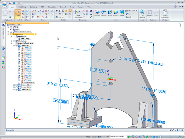
The big shift for ST3 is that you can model using both Synchronous and Traditional, (which Siemens is now referring to as Ordered) methods in a single part at the same time. Features are tracked in the feature tree, which is part of the Edge Bar, and categorised as either Synchronous or Ordered, and together play very nicely indeed.
You can use either method of working but, of course, some operations will always be better suited to an Ordered approach. You can also move your Ordered parts into the synchronous folder if you want to edit them in that manner. All in all the system now allows you to use what you need, when you need it.
However, one thing worth noting, which is actually quite difficult to describe in words, is that the system displays features as a split categorisation. But the interaction between those ordering features and the Synchronous driven operations is very powerful indeed, particularly with the almost instant rebuild and live rules.
It seems quite counter intuitive that an edit can be made using fairly standard operations which would have previously required a complete rebuild of a component.
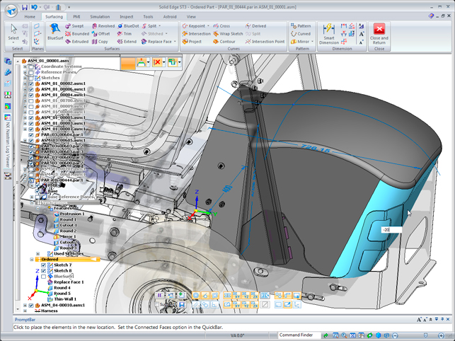
For example, editing a surface that defines a cut in a solid, which is then shelled. Experience tells you that editing the underlying surface would either require a rollback to that point or, at least, for the shell to disappear while the edit is made.
After all, it has been created a couple of operations after the surface. In the world of Synchronous Technology that doesn’t matter. If you edit the surface, the shell is still visible and they’ll all solve simultaneously as you drag geometry about. It’s impressive and incredibly subtle, particularly when you consider that the surface definition would have been an Ordered part and the rest Synchronous. Those working with these types of tools on a daily basis, will surely notice that there’s something magic in there.
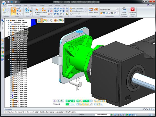
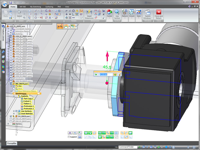
This fundamental shift caused by the removal of the split between the two methods also frees up the team to implement Synchronous working better with assemblies.
In the first instance, it’s now possible to manipulate geometry from multiple parts, drag and drop it into position. Also, you can define Synchronous Technology relationships between multiple parts by having geometry changes in one part drive those in another and, of course, assembly level features (such as the post assembly machining of holes and such) can be created where you need them.
Further extending this is the ability to work with a wider range of assembly-based modelling techniques using the direct modelling methods of Synchronous Technology, including frame design, weldment creation, pipe and tubing run creation and modification. Essentially, Synchronous Technology has not only become much better integrated into the whole of the system, but also now supports a typical user workflow.
User interface
While it’s not the leap that existing users saw in the first ST release with the move to the Windows ‘Fluent’ interface, nevertheless, in ST3 Siemens has listened to its users and made several improvements. Firstly, the pathfinder is no longer in its own panel in the interface, instead it’s presented overlaid over the modelling window.
While this might sound confusing, the UI team has done a good job of ensuring that it’s readable even when you have a screen full of geometry.
The Smart Step bar, which was made vertical alongside the edge of the screen, is now back to being horizontal and placed unobtrusively at the middle top of the modelling window. Also, a new customisable context sensitive ‘radial menu’ appears right next to your cursor.
This enables you to quickly pick frequently used commands without leaving the modelling window.
The final major aspect in the UI worth mentioning is the ‘Live Rules’ filter display tools, which are overlaid at the bottom of the modelling window. These give you immediate feedback about what’s currently active, what filters you’ve chosen and which ones the system has automatically found. This proves to be super useful when you’re using Synchronous modelling tools.
From 2D to 3D
Moving from 2D to 3D is an area that the Solid Edge team has been working on for many years in order to help 2D users leverage existing drawings as they migrate to 3D.
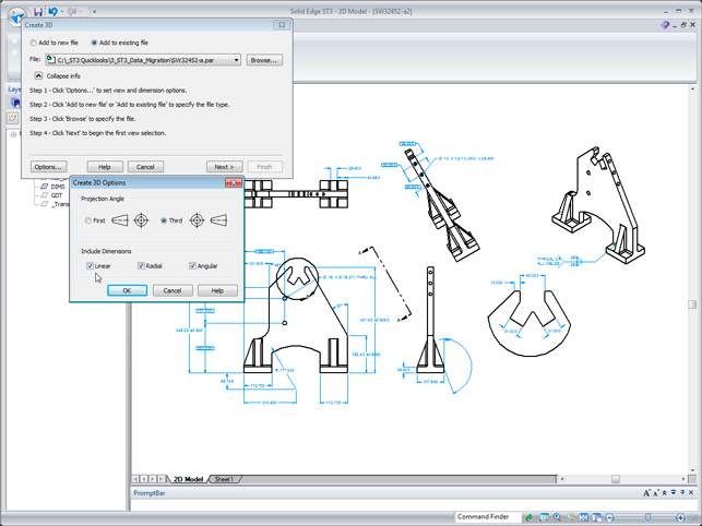
This has now been taken a step further in ST3, with users being able to take 2D drawings and 3D models from another system and transferring design intent captured on 2D drawings. This means that manufacturing dimensions such as distance between holes and overall height across multiple features, become the driver and not the dimensions of the model or sketch. Newly added dimensions are ready for editing and any geometric intent ‘lost’ in translation is found and maintained with Live Rules.
What it builds on is the glass box approach that many vendors use where 2D orthographic views are taken from the 2D drawing, arranged into 3D space and then used as the basis for quick creation of 3D models. What’s new in ST3 is that the solid model is read first, then the dimensions from the drawing brought across.
These are then attached to the 3D geometry resulting in a fully dimensioned model. If there are any discrepancies between the model and the drawing in the donor system there are tools available to re-adapt the forms and dimensions. Although this approach saves a lot of cross referencing between models and drawings, more importantly it’s the design intent of the drawing that drives the model.
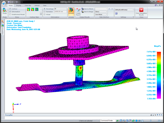
Real world simulation
Simulation is something that the Solid Edge team has been introducing into the product for the last few years, mostly since the release of Siemens’ very own Nastran-based FEA solution. The entry point is the Solid Edge Simulation Express that’s shipped with every Solid Edge Classic or Premium license and covers basic part static stress and modal analysis.
The next step up is the Solid Edge Simulation package for designers that’s either an upgrade or add-on for Solid Edge Classic. However, the most cost effective approach is to buy the Solid Edge Premium package, which also includes XpresRoute (pipes and tubes) and Wire Harness.
This release extends the conditions which can be automatically set-up, specifically the ability to define torque and bearing loads as well as bolted connections. There are also unique tools to assist with abstracting the model or removing details that are unnecessary in the simulation process, such as rounds, smaller holes and fillets.
This works in a pretty automated manner in which you select the geometry and remove the features you don’t want. You can then store this as a ‘simplified’ part which can be automatically maintained during design changes and subsequent simulation studies.
In conclusion
Prior to Solid Edge ST3 Synchronous Technology was only available in two major releases of Solid Edge. While the first two indicated the direction that Siemens wanted to move in, it’s now with a third major release that the mists begin to clear and the work over the past three years starts to mature.
Simply put, users do not have to decide which modelling method they wish to use before even starting to design a part. Being able to mix and match both Ordered and direct editing operations in a single part truly shows how this type of technology can aid the designer.
There are often cases where an operation that should be simple, can’t be carried out because of the weight of the history tree above it. Equally, there are many instances where a more ordered approach to design is required that direct editing can’t handle. I’m not talking about complex paramterisation but simple geometry edits.
ST3 looks to solve many of these instances because you do have two options, at all times.
In a wider industry context many vendors are currently chasing the integration of structured history-based modelling tools with more freeform direct editing approaches. For instance, Autodesk is pursuing its Inventor Fusion technology whilst PTC has Project Lightning coming on stream shortly (this review was written prior to the announcement in October). However, no one has really shown what can be done – until now.
Solid Edge is often viewed as the third place player in the mainstream modelling market, but Synchronous Technology has changed that.
The system is now getting more mind share from an increasingly savvy user community looking to solve problems often caused by limitations of current modelling practices. Many see the 3D design world as being a mature and staid industry, but releases like Solid Edge ST3 make it clear that there are still many challenges to overcome.
Innovation is still possible if a vendor talks to its customers and finds a robust and elegant solution to help them rather than just showboating the latest widgetry. I can’t applaud this release more.
| Product | Solid Edge ST3 |
|---|---|
| Company name | www.siemens.com/plm |
| Price | On application |