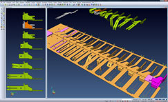
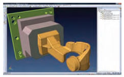
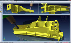
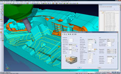
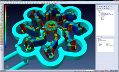
The progressive die design tools have seen a lot of attention over the last few releases and VISI 20 introduces more updates such as the ability to pull in components and quickly assemble standard components from supplier catalogues, templates and of course, user defined set-ups.
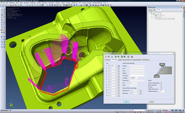
VISI 20 CAM tools for wire electro-discharge machining processes
While the basic use case follows a prescribed process, that workflow can now be stepped out of and special cases dealt with — whether that’s adding plates or adapting components.
Work has also been done to the unfolding/bending process to better support working with smaller components.
Those that work within the progressive die industry will be familiar with the use of middle skins to assist with the unfolding of complex parts with small fillets that throw off the blanking process. These new tools should make it more robust in this environment.
VISI Wire
Alongside the tools for developing forms for production and manufacturing, VISI also has a growing set of CAM tools for programming a variety of machines and processes.
While we’ll deal with the milling aspects momentarily, it’s worth noting the updates that have been made to VISI Wire.
These tools, which are aimed at those working with wire electro-discharge machining processes, now introduce automatic detection of undercut conditions where the offset is larger than the radius of the arc.
Part of this problem revolves around finding these conditions in the first place, but also dealing with them. These areas can be fixed using automatic tools or diving in and doing it manually.
There are also tools for automatically adding corner relief to parts according to a prescribed standard.
Elsewhere, start holes (where the wire is initially passed through the material) can now be reported to the user separately as a graphical set up sheet or NC file.
Another machining related update to VISI Wire is the addition of greater taper control. This is now done per cut, rather than the part as a whole and consolidates multiple operations into a single command allowing the user to generate more complex forms.
The final wire related update is the ability to output specific M/G codes, with comments, so that the code looks exactly how the user expects.
Whilst this means the function of the code can be changed, users often want to make ‘cosmetic’ changes so it’s more familiar. A small thing, but for those with years of experience, vital.
VISI Machining
Of course, the big attraction of VISI for many is its comprehensive set of tools for producing machining toolpaths for a wide variety of machine tools, from basic drilling cycles to highly complex five axis beasts.
We’ll get onto the toolpath and machining operation specific updates in a moment, but first, there’s one big addition to the system that will make life easier for many users.
The model/toolpath window now displays all the relevant information and guidance about the current task that is being worked on.
As with the file preview we discussed last month, the on-screen display provides data such as project details, machining operation, tool type, part material and speed and feed conditions. Importantly, all the information is configurable and can be tailored to the user’s own preferences.
Speeding calculation
As those with machining experience will probably know, the toolpath calculation for anything other than trivial and simple parts is often a computation intensive activity.
Whether it’s down to machining complex features in a prismatic part or creating efficient toolpaths for cutting complex surfaces — time is often required.
Vero has been working to allow more of its multi-threaded operations to take advantage of today’s multi-core and multi-processor machines, but often, when the pressure is on, that’s not going to be enough.
With this in mind, this release introduces Hive Computing. While it’s got a fancy name, it’s essentially an ad-hoc networked cluster that allows a company to use spare computational capacity on its network to farm out and calculate toolpaths — whether that’s overnight, over the weekend or just when it’s needed.
What’s interesting is that there’s no additional cost or license required. Set-up is simple, requiring the network path to each machine along with the number of processes or threads on each machine to be used.
The system then sends a separate executable for each machining operation to the appropriate machine for calculation, which is then returned to the master machine when complete.
Dynamic Incremental Stock
This is a big update, particularly for those working with multiple set-ups and multiple operations. It centres around the use of a continually updating stock model.
The concept is that, as each operation is completed, a simulation is performed and the remaining material found, stored and passed onto the next operation.
This is called the incremental stock model and it allows each operation to know exactly where material remains and where it needs to cut. This reduces the time for each operation by dramatically reducing fresh air cutting.
What differs between each system is how that stock model is calculated. Many systems, including previous releases of VISI, used a top down approach, meaning that the stock model wasn’t particularly useful for parts that required machining operations from multiple directions.
What’s different now is that VISI uses a closed stock model that’s maintained across the operations and provides an accurate representation of the part’s current form.
Datum shifts
This is another big update for those working with complex machining set-ups.
When setting a machining datum on a part from a large assembly (from where all 3+2 and five axis angles are calculated), this previously required the part to be moved to the absolute CAD reference.
To explain this — take part of a suspension assembly for example. The part might be referenced within the assembly to the front wheel but the part itself would need a local datum for machining.
To overcome the need to move the part within VISI 20, the user can now create any local datum and set this as the absolute reference for all machining procedures.
This has many benefits, including the ability to automatically re-compute all machining angles for 3+2 and five axis operations if the local absolute machining reference is moved.
This means that the part does not even have to be rotated to machine underneath the part but just a new absolute machining datum created.
Feature recognition
Feature recognition tools, which are used to find commonly machined features such as pockets, holes, bosses etc, now give priority to how the components should be machined (looking at features from a Z level perspective), rather than how they’ve been designed.
This means less tinkering with operation and set-ups because it has a greater understanding of how parts are manufactured, rather than modelled.
The feature finder has also been expanded to recognise additional geometry such as tapered pockets.
Toolpath editing
This is another big one for those looking to make their machining operations as efficient as possible.
Users can now dive into the underlying toolpath geometry, grab individual passes and remove them, change their order, split into smaller strokes or even group them with other passes, having the system re-link the remainder together again.
All edits are collision checked with the system adding safe moves to avoid geometry if necessary.
Rapid moves can also be quickly and globally adapted without needing to recalculate the complete toolpath. They can also be modified individually — all collision checked as the user makes amendments.
What’s key is that when inevitable changes occur and the need arises to recalculate the toolpath, this editing happens post-calculation. It means that the user will lose them with any updates to the underlying toolpath — and rightly so.
Machining operation updates
High speed spiral roughing: The last VISI release introduced the concept of hybrid machining, where multiple machining strategies are mixed into a single operation.
This release follows up this work by adding knowledge about cutter engagement at all points in the operation.
This means that toolpaths can be made to engage as much or as little of the cutter as the user chooses.
If they want to go all out and use 100 per cent of the cutter diameter, it will be a quick operation because using large step overs means that extra ‘pip’ moves are added into the corners where there would possibly be up stands of material left.
The toolpaths are also intelligent enough to know that it’s safe to stay down on the part and move within its previously cut operation, reducing the need for Z retract moves.
The HM Roughing toolpath will also adapt Z depths to flatten off any areas that fall in between step down moves. This type of thing isn’t for everyone, but is particularly suited to those working at high-speeds with convex cutters that have gained popularity over the last few years.
Rest machining as finishing operations: Users can now use pencil machining strokes to create the layout of rest machining operations.
These can then be tweaked, split, reordered and adapted to get the toolpath exactly how the user wants it. It’s this type of control that separates out the advanced/high-end machining applications from run of the mill CAM systems (pun absolutely intended).
The goal with this workflow is to not only refine and iterate the machining process and improve cycle time, but also for it to impact on the surface finish as the user can control steep and shallow areas to a very granular level.
ISO machining: Using wireframe geometry as the basis for subsequent machining operations.
One perfect use is that it’s common to machine rib like features in a core/cavity with a single stroke, instead of producing electrodes, which is the width of the cutter.
In VISI Machining the user can now grab the curve (from the bottom of the rib) and use this to define the operation, including where the curve is offset from — left, right, centre.
When multiple offsets of the toolpath are added in Z (rib roughing) it’s possible to trim the ISO toolpaths back to the stock or CAD model.
Swarf cutting: This is another one that’s been in the system for a while, but again, there’s room to add greater flexibility.
Swarf cutting, for the uninitiated, is cutting at 90 degrees to the end of the tool to remove material.
It’s commonly used in the turbo machinery market for the machining of blades or blisks.
The operation is easy to define and has been redesigned to make it specialised for that purpose guiding the user through the selection process. This reduces set-up time and, when combined with greater control over the selection of geometry from the model, more powerful.
Conclusion
Taking stock of the things we’ve discussed in this manufacturing focussed review and the other, design focussed one, a couple of things become clear.
The first is that Vero is doing an excellent job of not only evolving the existing set of tools but also adding new functionality and capability in many areas.
Evolving feature sets see existing tools not only consolidated into more efficient workflows, but also made more intelligent.
This will make life easier for existing users, but also make the learning curve shorter for new adopters.
In terms of new functionality, it’s clear that Vero is thinking things through and listening to customers about the challenges they’re facing with regards to preparation of data for manufacture, for new processes and machining techniques they’re using.
If you’re looking for an integrated set of tools for design and manufacture that covers all your bases, then VISI should be on your short list.
VISI Flow: Simulating conformal cooling
Alongside the design and NC preparation tools in this release, another key part of the VISI tool-set is VISI Flow.
Acquired a good few years ago now, the system has gradually been brought into the VISI application set and is now well integrated in the environment.
For this release, there’s been a lot of work done under-the-hood to make the system more efficient and 64-bit compatible.
Elsewhere there’s a completely redesigned material database that includes 9,000+ materials. The new filtering and searching tools enable the user to drill down and find the exact polymer they’re looking for.
The redesign also has benefits upstream in that the same interface is available to the design team to aid the task of finding polymer shrinkage values and the like.
In terms of new tools for simplifying the calculation setup, there’s a new moulding machine environment.
This allows the user to select from a database any capacity injection press, which then in turn automatically enters calculation limits, to ensure the component can be moulded within the capabilities of the moulding machines.
Alongside these tools, the big update for VISI Flow is the ability to simulate conformal cooling channels.
This approach has been around for quite a while and describes the process of designing cooling channels that better match the form of the user’s core and cavity, rather than using linear drilled holes. It offers more uniform cooling and better cycle times.
Now using VISI Flow, the user can define conformal cooling channels using a 3D model and add it into the simulation.
Of course, this type of work is often done as an insert into more standard tooling plates, which means that the user can combine traditional drilled cooling circuits and 3D printed inserts in the same model.
| Product | VISI 20 |
|---|---|
| Company name | Vero Software |
| Price | From £2,000 |


