
FeatureScript is a big deal. In fact, I think it’s the single most important feature of Onshape.
With FeatureScript I can do with one custom feature what took two dozen features before and, by building a library of features for common tasks, I can build using ten features what used to take a hundred.
As a result, my parts are faster to rebuild and also easier to understand, build, and modify.

MCAD systems are typically designed with a set of highly generalised features for generic shape creation: extrude, revolve, sweep, loft, etc. With these tools you can design just about anything, but it’s a long, painstakingly manual process.
Some intrepid entrepreneurs build specialised plugins for, say, ship design. These plugins add a layer of more specialised tools specifi cally designed for ship design, and that’s great for ship designers.
But what if your company specialises in gearboxes for wind-up toy chickens? Is there a wind-up toy chicken plugin for SolidWorks? Alas, there is not. And writing a custom plugin for a desktop MCAD system can be a time-consuming process. Most users resign themselves to building everything with those lowest-common-denominator tools: extrude, revolve, sweep, loft. Sigh.
Enter FeatureScript
FeatureScript is not a mere scripting layer resting atop an MCAD system; it’s deeply integral to the way Onshape works. Internally, Part Studios and sketches in Onshape are just big FeatureScripts. Every tool in the Onshape toolbar is written entirely in FeatureScript. Perhaps most exciting is that every tool in Onshape is now open-source for all to see, released under GPL for your hacking pleasure, a fi rst in the MCAD market.
FeatureScript is great for automating repetitive modelling tasks like holes, slots, fasteners, injector ports, or hinges, but its real power is in building larger structures with parametric generative patterns: framing, trusses, lattices, conveyors, escalators, staircases, grilles, knurls, linear actuators, gearboxes, nozzles, chains, perforations, wire meshes, saw blades, bearings, plumbing. Anything that you model frequently could be a FeatureScript feature, and the more complex and repetitive the task, the more time it can save.
Recently, for example, I was tasked with building a Kort Marlin 19A nozzle for a twoman submarine propeller. (True story). As it turns out, the Kort nozzle profi le spec simply scales based on propeller diameter. As such, I should never need to model a Kort Marlin 19A again.
In Onshape it was trivial to import the model into a FeatureScript, add a propeller diameter parameter, and from that moment onward have a “Kort Marlin 19A” feature in my Onshape toolbar. The nozzle appears in my feature manager as “Kort Marlin 19A,” and double-clicking it lets me edit the propeller OD parameter on the fly. Clean, fast, easy to understand, easy to modify.
But the real time savings come with more complex designs. Let’s say you’re a factory automation designer, and each fl oor you design has at least a dozen conveyors of various lengths, widths, heights, and angles. What if building an entire conveyor – complete with rollers, bearings, and fasteners – were as simple as adding a single Conveyor feature with parameters for length, width, height, and tilt? You could add other confi gurable parameters for roller size and spacing. Now you can build an entire factory fl oor’s worth of conveyors in the time it takes to microwave a cup of cold coff ee.
But of course it’s not quite that simple. FeatureScript is, after all, a scripting language. As elegant and well thought-out as it may be, there’s always a learning curve.
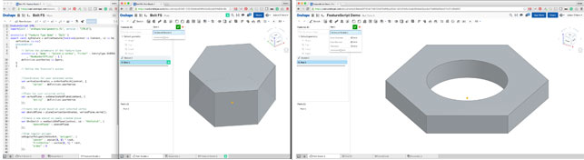
Now we’ll build the very beginnings of an extremely simple FeatureScript: a lowly hex nut, starting with the basic shape.
Tutorial
Learning to code in a new language can be tricky, especially if you aren’t already a coder. To make it easier, there’s a video version of this tutorial here. You’ll also find the full, completed code posted there for your copy/paste pleasure. This tutorial assumes a basic understanding of Onshape, creating a FeatureStudio, and running FeatureScripts. For more on these topics, click here.
Setup
FeatureScripts always begin by clicking the “New Feature” button at the top of the editor. This drops a simple snippet into the code as a starting point.
There are three parts to this code: the declariation (top two lines), the precondition, and the actual body of the feature.
annotation“Feature Type Name” : “Nut” }
export const nut = defineFeature(function(context is Context, id is Id, definition is map)
precondition
{
// Define the parameters of the feature type
}
{
// Define the function’s action
});
Query filters
The Query interface is quite possibly the single most important concept in working with FeatureScript. Queries allow our code to access geometry in the Part Studio.
precondition
{
annotation {
“Name” : “Point”,
“Filter” : EntityType.VERTEX && SketchObject.YES,
“MaxNumberOfPicks” : 1
}
definition.point is Query;
}
A query parameter like this asks the user for a piece of geometry. By adding a “Filter” tag, we tell Onshape that it should only accept geometry with certain characteristics, in this case sketch vertices.
The && operator is a common programming convention meaning “AND”. In this case, it means that our filter requires that any user selection be both of EntityType.VERTEX and that it have the property SketchObject.YES. Any selection that doesn’t meet both of these criteria will be rejected.
Evaluate functions
Queries are just little street signs pointing to certain geometry, but are not geometry in themselves. When we query a sketch vertex, for example, the variable “definition.point” does not refer to any actual piece of geometry, but rather to a street sign that points to a piece of geometry. In order to learn about the geometry itself, we need to evaluate the query.
var origin = evVertexPoint(context, {
“vertex” : definition.point
});
debug(context, origin);
// prints a vector() with the xyz coords of the selected vertex
In this case, we’ll use the evVertexPoint() function, which accepts our query as input and returns a vector with the (X, Y, Z) coordinates of our vertex.
Maps
Finding our sketch normal is slightly more complex. Retrieving the sketch normal actually happens in two steps: 1) get the sketch plane for our queried vertex, and 2) find the normal of that sketch plane. In order for this to make sense, we first need to understand maps in FeatureScript.
// A ‘map’ in FeatureScript is just a bunch of key:value pairs.
var fruitColorsMap = {‘apple’: ‘red’, ‘banana’: ‘yellow’};
// We can access members of a map using dot syntax: mapName.key
debug(context, fruitColorsMap.apple); // prints “red”
This concept is very common in object-oriented programming (OOP) languages, and you’ll use it heavily in FeatureScript. In fact, every single FeatureScript you write makes use of a map: the definition variable. Remember how we define our parameters using definition.whatever? That’s because definition is a map variable, and it contains a bunch of key:value pairs, one for each parameter in our function.
// Structure of a Plane map
var plane = {
‘origin’: vector(0,0,0),
‘normal’: vector(0,1,0),
‘x’: vector(1,0,0)
}
debug(context, plane.normal) // prints vector(0,1,0)
A Plane object in FeatureScript is just a map containing three key:value pairs: an origin vector, a normal vector, and an x-direction vector. Since the plane is just a map, we can access the normal vector using dot syntax: plane.normal
Sketch plane normal
Back to the task at hand: finding our sketch plane normal. evOwnerSketchPlane() function accepts our queried vertex and returning a Plane object. Since our plane object is just a map, we can access its normal vector using dot syntax: evOwnerSketchPlane(). normal.
var normal = evOwnerSketchPlane(context, {
“entity” : definition.point
}).normal;
debug(context, normal);
// prints vector() with the sketch plane’s normal direction.
Sketch
There are three steps to creating any sketch in FeatureScript:
• Create the sketch object
• Add geometry to the sketch object
• Solve the sketch
Once we’ve done those three things, our sketch becomes usable to other features in Onshape.
The sketch code in our example is fairly self-explanatory: we create a sketch on a plane, draw a couple of shapes, and solve the sketch. The only important thing to watch out for is the creation of the sketch ID. All features in Onshape should have a unique ID. We’ll talk about ID objects in more detail in another tutorial. For now, just know that each feature you create in FeatureScript needs to have a unique ID that looks like this:
// All features in FS should have a unique ID appended to the id object
newSketchOnPlane(context, id + “somethingUnique”, definition);
Once we know that, the rest is easy. Sketch operations in FS begin with ‘sk’, so it’s easy to search for them in the code auto-completion.
// create sketch on plane
var theSketch = newSketchOnPlane(context, id + “theSketch”, {
“sketchPlane” : sketchPlane
});
// draw stuff
skRegularPolygon(theSketch, “polygon1”, {
“center” : vector(0, 0) * inch,
“firstVertex” : vector(0 * inch, definition.od),
“sides” : 6 }); skCircle(theSketch, “circle1”, { “center” : vector(0, 0) * inch,
“radius” : definition.hole
});
// solve sketch
skSolve(theSketch);
Extrude
Extruding things is easy, but there are two different extrude tools in FS: ‘extrude’ and ‘opExtrude’. As a best practice, use the latter.
The ‘extrude’ feature is the one you see in the toolbar. It has lots of extra code in it for working with the UI, and once it’s done that it just calls the ‘opExtrude’ command. That means that ‘extrude’ is really just an extra layer of icing you don’t need on your FeatureScript cake. Rather than use ‘extrude’ – which just calls ‘opExtrude’ anyway – it makes more sense to just use opExtrude directly.
// extrude sketch regions created by: id + “theSketch”
// the ‘true’ parameter tells opExtrude to ignore inner loops,
// thus keeping our circle from being extruded
opExtrude(context, id + “extrude1”, {
“entities” : qSketchRegion(id + “theSketch”, true),
“direction” : normal,
“endBound” : BoundingType.BLIND,
“endDepth” : definition.thick
});
Cleanup
IT’S ALIVE! Our code works. It creates a Plane object, puts a sketch on that plane, draws some geometry in the sketch, and extrudes the sketch. Awesome.
But the sketch was really just a means to an end. We don’t really want it in the final result, we just need it during construction. To get rid of the sketch (and anything not needed), we can use the ‘opDeleteBodies’ operation.
(Note: like the ‘extrude’ function above, there is a ‘deleteBodies’ function in Onshape. The same best practice applies to this as to extrude: it’s better to use the deeper opDeleteBodies() operation than the higher-level deleteBodies() feature).
// delete all bodies created by the feature: id + “theSketch”
opDeleteBodies(context, id + “deleteBodies1”, {
“entities” : qCreatedBy(
id + “theSketch”,
EntityType.BODY
)
});
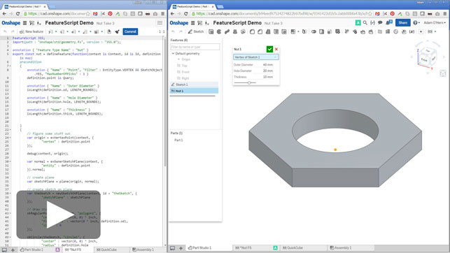
Parameters
Last we add our UI parameters. This might seem backward, but I find that anything I can do to decrease cognitive load while coding is a good thing: my cognition can only carry so much load! By trying to think about the UI and the guts of the program at the same time, I get confused, frustrated, irritable, and generally unpleasant.
Instead, I prefer to do the simplest possible code, with static values for dimensions. That way I can focus my attention solely on the business logic of the code. Once I’ve done that, I can backtrack, adding in UI details as needed.
You may find a different method works better for you, and that’s okay. My experience has led me to work in a very iterative way, beginning with simple code, augmenting it, and then re-writing it from scratch over and over again. That might seem like a lot of redundant work, but I’ve found that I get better results that way than trying to anticipate every possible problem in advance. Do whatever works for you.
Note: Units
Length variables in FS are typically created by multiplying a number by a unit. The implications of this are a bit odd at first, but workable.
In our example, our hexagon’s firstVertex parameter defaults to a vector() multiplied by a unit (inch). This works as long as both of the vector values are numbers.
definition.od is not a number, however. It’s a length, and you can’t multiply a length by a unit. So for this to work, we have to change the structure of the statement.
// before
vector(0, 1) * inch;
// incorrect:
// vector(0, definition.od) * inch
// correct vector(0 * inch, definition.od);
Full code
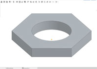
In only a few lines of code we create a full-fledged Onshape feature that creates a simple hex nut shape centered on a given sketch vertex, and using a user-supplied outer diameter, hole diameter, and thickness. A production feature would be more complex, including standard nut sizes, threads, fillets, orientation options, and the ability to place multiple nuts in a single feature. I find that it’s best to work iteratively, beginning with the simplest-possible code and gradually adding complexity.
For the full code and to see the rest of this tutorial series, including a video version of this tutorial, Click here If you’re interested in learning more about the strengths and limits of FeatureScript, email adam@cadjunkie.com
Adam O’Hern

Adam is a product design consultant. He’s helped design and visualise laptops, power tools, audio gear, educational toys, a robot, a hibachi grill, a cooler, headphones, faucets, toilets, flush valves, a sci-fi movie vehicle, coffee makers, a panini maker, a lint roller, gaming consoles and accessories, drones, golf clubs, medical devices, VR headsets, and a scrubber thingy.
Our tutorial for what you can do with it, and how to get started
Default


