

Siemens PLM Software has one of the biggest product development software portfolios, but its mainstream design tool Solid Edge and the PLM-focused Teamcenter tend to grab most of the headlines.
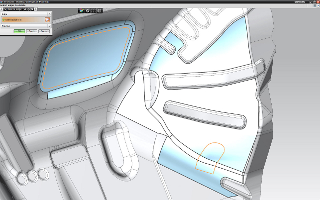
Geometry modification in a typical automotive component created using surface modeling techniques. Cleaning up data is simplified with Synchronous Technology, with the user simply electing the edges and the resulting cutout removed
This is a shame as, for me, NX is the one to watch. Originally born from the amalgamation of two established tools, Unigraphics and I-DEAS, it has grown into a breathtaking product development system in its own right.
Now on its eighth major release, the system continues to impress, so let’s looks at the highlights.
HD3D & Visual Reporting
NX 7 and the point releases that followed saw tools introduced that allowed users to dive into the wealth of information held within product models and associated
metadata and present it easily and visually in glorious 3D.
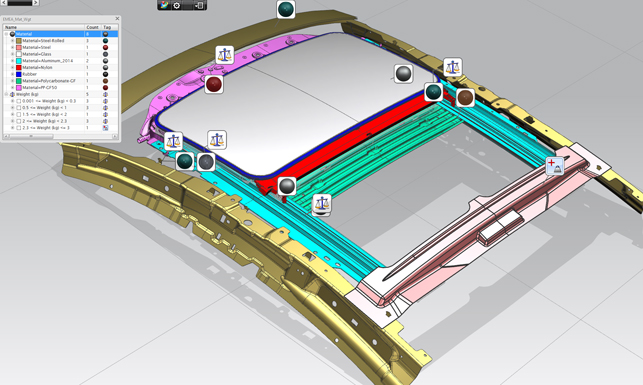
This could be anything from a change state, to a material or weight. In fact, if it could be held within the CAD model or PLM system, it could be shown in context on the 3D model using colours and tags.
These visual reports could then be saved, reused and shared. With the NX 8 release data can be pulled from a much wider range of sources with server-side reporting. This means that in addition to taking
data from both NX and Teamcenter, visual reports can now be created with data from Enterprise Resource Planning (ERP), Material requirements planning (MRP) and finance systems.
In addition, it’s also possible to combine reports and tailor tags with custom bitmaps. While this might sound a little trivial it can be a very powerful way of understanding exactly how a project is progressing.
The software can track sub-systems to find out which ones are over running or over budget and the information presented alongside a photo of who is responsible. Weighting and costing data could be combined to those sub-systems or components that are contributing the most cost. The possibilities are endless.
Visual Reports that were previously separate can now be combined (two or three is probably the optimal) to create rich, incontext information. Each contributing input can be given a priority from low,medium to high and these composite reports can be saved, distributed and reused.
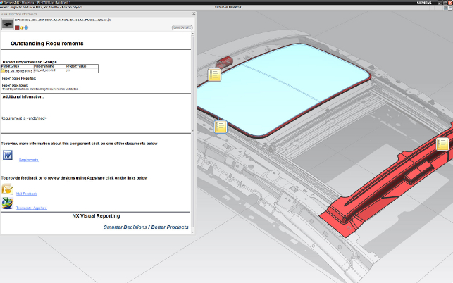
The other interesting update to NX 8 is the ability to drill down deeper into the information presented. The new Info dialog allows the user to look into the details of the data presented in the Visual Report, whether that’s quickly viewing requirements documents or providing mail feedback using AppShare to discuss things with the project team.
All these tools can be built directly into the reports, making them as usable as possible and helping guide users through their tasks without having to worry about what extra systems or processes are used.
Automating CAE with Product Template Studio
NX has always featured knowledge capture and reuse tools in the form of Knowledge Fusion, but this required a heavy amount of custom programming.
With the introduction of the Product Template Studio (PTS) tools usability was taken to the next level and non-specialist users could define a process based on an existing part or sub-system and reuse it at will.
In previous releases, the PTS tools were only capable of automating the design of geometry, capturing the rules, parameters and inputs in a simple workflow.
In NX 8, it’s now possible to build many more downstream tasks relating to the design process, rather than just pure geometry wrangling and manipulation. This could be assembly design, building and positioning assemblies, geometry checking or CAE studies.
Once the work has been carried out, it can be brought into the Template Studio where the parameters and inputs can be pulled out, linked to a dialog, and a template built and deployed for reuse.
Patterning
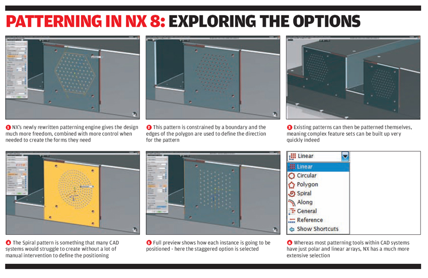
Now this might look like an odd one, but the patterning tools in NX are pretty hardcore. While other systems just support linear or radial arrays of features, NX takes things to the next level. Full control of everything is provided to get a pattern just how it’s needed.
There are different repeat patterns as well as distinct arrangements such as linear and polar, together with spiral, polygon based and along curves. The user has control over how each instance is positioned and there is also the ability to switch instances on and off.
There are also some interesting tools for using boundaries to define where instances are placed. Variational patterns can be defined to get graduated patterns or indeed, read in positioning data in from a spreadsheet.
All in all, the patterning in NX is first class and could save some serious time for those working on highly complex parts such as electronics enclosures.
Synchronous Technology
Those that follow trends in design technology will no doubt be aware of Synchronous Technology and the changes it signalled in the design system industry when first introduced four years ago.
The move to integrate direct modelling technologies, and much more besides, changed the way users both perceived and used design tools. While some form of direct modelling technology appears in most popular design tools, the way Siemens has implemented it in NX through Sync Tech has always been different.
For example, Solid Edge took a partisan approach that split the system into a Synchronous and traditional historybased approach. With NX, Sync Tech was integrated into the existing toolset to such a level that many users weren’t even aware they were using them — to my mind, a much more intelligent method.
The last few releases of NX have seen the Sync Tech tools mature and these are now even more deeply embedded within the software allowing for the use of whichever method of modelling is most appropriate.
For the NX 8 release, Siemens has concentrated on working with more complex geometry conditions. As always when discussing direct modelling tools, the first instance is when working with fillets and blends. While demonstration data always shows seamless edits to geometry, in the real world complex corner conditions can very easily throw off a direct modelling system.
NX now has tools that enable the user to work with them and make the edits needed. Whether standardising, adapting rounds to ease machining of tooling or preparing a model for CAE, there’s something there for everyone.
Work has also been done on providing the same types of tools for sheet metal forms. Edges can be deleted quickly and will work across multiple surfaces. But here’s the thing — because the system works with imported data and stores each operation as a feature, the user can update the imported file and propagate the changes very quickly to accommodate a design change (of course, assuming the references stay the same).
The final major Sync Tech update relates to the editing of parts using a section, rather than edge and face geometry. Whereas in previous releases, a section would be taken through a part and then used to drive geometry edits, in NX 8 these tools can also be used within history-based parts.
Section-based editing, which was introduced with Sync Tech, is now available with the history-based modelling. It’s possible to dive in and edit the geometry by cross section and have an additional feature appended to the end of the tree.
The same tools also support working with cross section dimensions on a geometry set after the fact, rather than trying to work with complex parameters.
Conclusion
When you’re searching for a state of the art of tool to assist with product development, there are very few places better to look than at NX.
The work done in this release on core modelling tools demonstrates that there’s still room for innovation in raw geometric modelling. And from speaking to many users, it’s clear that they are being adopted and used, even if the user might not be aware that they are.
Then there’s tools like the new patterning toolset, which has been completely rewritten. Yes. In 2011, I’m getting excited by patterning. The fact is that most systems only pay lip service to the creation of these types of features that can cause real headaches for users.
The new tools in NX 8 let you create the geometry you want, with the control you need, to develop your concept. Alongside these core tools, there’s a heavy focus on two other areas.
The first is in workflow improvement and knowledge capture — two things that are heavily interlinked.
What’s the point in striving to capture knowledge of how standard practices are carried out if the mechanism to reuse that knowledge is clunky and inflexible?
That’s what the Product Template Studio solves. It lets an organisation formalise specific instances of its knowledge and experience into efficient workflows that guide the user (or re-user) through the process of designing a specific part or sub-system. But it also gives the user the ability to step outside of that almost wizard driven workflow to make changes to suit a specific design challenge.
Also related to this is the new Part Modulefunctionality, which enables a team to work on a single part in a controlled manner that supports the design and review process. And while its use will be limited, I would imagine, to those working on highly complex parts, it’ll be a fantastic productivity tool.
Then there’s the HD3D technology. Now this I like a great deal. From a management perspective, the ability to dive into the complex and often obscured data that resides in a company’s many information management systems (whether that’s PLM, ERP, MRP etc) and have it consolidated, presented within the context of a 3D rich environment, makes huge sense.
But what of the designer or engineer at the coal face? I believe the tools hold value there too. The ability to pull data into a 3D model and associate them to the product you’re working on, whether at a macro or micro level, at the part or sub-assembly level, is incredibly powerful.
Being able to pull up a report that instantly shows where bottlenecks are, where weight is gaining, perhaps even who is working on what part so you can phone them, is a powerful tool indeed.
NX has always been one of the most interesting systems to watch develop and mature. While we’ve only covered the headline updates here, there’s much, much more to NX 8 in terms of CAE and simulation and manufacturing.
One of the best compliments I can give Siemens PLM Software is that when I work through the updates, I’m never left with the question of “why would a user want that?” It’s always clear.
There’s always a challenge to solve, whether it’s at an organisational level in terms of workflow and process or at the coal face of designing complex geometry. We can’t really ask for more than that, can we?
Part modules
Part Modules is brand new territory for NX. Many of Siemens’ larger customers, particularly within the automotive and aerospace world, are constantly facing the design of highly complex and large components — think Body-in-White work in the automotive industry or stamping die design — pretty much anything that requires multiple team members working on a single component.
Now, while today’s higher-end design systems (such as NX or Catia) have tools to allow multiple team members to work on multiple parts within an assembly, the same can’t be said of single parts. To assist with this, NX 8 sees the introduction of Part Modules, which is a pretty complex concept to explain.
Imagine you have starting reference geometry for a part that needs to be designed by multiple team members. A good example is an air frame component for a fuselage. The references would typically be the outer skin on the fuselage and positional references for the mid-plane.
This is used as the master part and the work is split into two parts. Another example is electronics devices, where the form is lead by the ID surfaces with the engineering and production detailing following on.
The process requires the creation of separate work files containing the reference geometry each team member will need. These can then be imported as a part module for the work to be carried out. Once complete, or at a stage where the data needs to be remerged and rationalised, each user defines the ‘output’ geometry and with it is then sent back to the master model.
Of course, this not only means actual part geometry, but also any further reference geometry needed by other parties. I would imagine that this type of tool is going to be used in a controlled manner, so it’s good news that the whole process can be managed by Teamcenter — both in terms of data versioning and work and task assignment.
| Product | NX 8 |
|---|---|
| Company name | Siemens PLM Software |
| Price | on application |


