

Non-contact optical digitizing specialists, GOM and Physical Digital, take a closer look at an inspection workflow for those working with injection-moulded parts
Today the tools to produce injection-moulded parts are often built from purposely-modified, CAD data. These modifications include the incorporation of uniform and non-uniform shrink factors, adding of draft angles, parting lines etc.
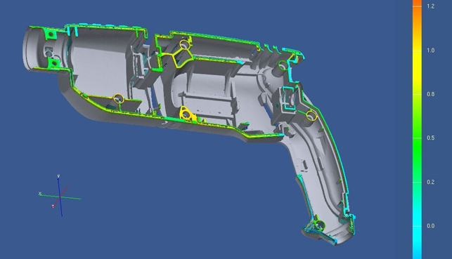
Deviation of the parting surface of the actual part to a plane. It shows deviations of up to 1.2mm
Best practice knowledge is also incorporated to reduce thick versus thin material areas and the possible addition of features to reduce the warping and twisting of the part. Using these basic rules, tools for simple parts can usually be calculated and milled to produce good quality parts, with no further modifications needed.
But complex parts with tough accuracy, quality and delivery requests are needed frequently. These parts need a first article inspection and periodic or continuous quality control.
The quality control team has to quantify the first sample parts and give the “go” for the production. Then in addition they have to monitor the quality of the product during its complete life cycle.
For the first article inspection, the parts have to be comprehensively tested and verified to quantify the “As Built” condition.
This information can be utilised to incorporate immediate design / manufacturing changes to produce a good part and can also be used as a baseline data set to monitor future part production.
To ensure the production quality, the wear on the tool and form modifications of the produced parts have to be measured and visualised as early as possible, at minimum costs.
To measure the form of a part on a CMM (coordinate measuring machine), the part has to be fixed and aligned to the measuring table in the appropriate coordinate system and is measured in a best case scenario of a maximum of a few hundred measuring points. Based on this sparse measurement information, the decision regarding the product quality and the “go” or “no go” of the production has to be taken.
If the part does not meet the expectations, the quality team has to identify the area of concern and define the cause of the problem. Often measuring data from multiple parts which, when assembled, produce the product; have to be considered to understand the cause of the problem. Therefore a measuring sequence can take several days until exact guidelines of how to correct the tool can be defined.
Today innovative companies are utilising digitizers to speed up the first article inspection process and minimize the effort needed to confirm the product quality. Using these digitizers, stable parts can be measured completely, efficiently and with high data density (millions of measuring points) without the need to produce and manage individual fixtures.
Parts can be digitized as they are or in an assembled configuration as well as under load to define their form and deformation and behaviour in use.
The digitized data points are available for a graphical display of the actual form, “As Built” condition, and its deviations against master data (CAD data or digitized data from a master part). The data can be “registered” with individual rules into the master data to visualize global and local deviations.
As the digitized data can be gathered, stored and reloaded easily, individual measuring values and sections can be derived and analyzed from these data at the user’s convenience.
The first article measurements and subsequent following measuring sessions made to ensure the product quality during the production generate a data set over the whole product lifetime, making wear and changes in the production process easy to verify and control.
Digitisers that are used in quality control applications have to produce reliable and accurate data. Scanners with two cameras in a stereo setup respond perfectly to this need.
The additional data from the second camera is used to verify the system’s calibration, generate highly accurate data and detect and remove poor data. Movements of the object or the digitizer and changes in the ambient light during the data acquisition are also detected. In addition the stereo setup defines reference markers with high accuracy.
Based on these markers, the individual views are automatically registered into each other, without any “best fitting” on the digitized data.
If the dual camera digitizing system becomes de-calibrated, the system can be re-calibrated by the user, taking stereo images of the certified calibration panel (delivered with the system).
With an ATOS digitizing system, for example, the same calibration procedure (two to five minutes) is needed if the customer would like to adjust to a bigger measuring area, e.g. to digitize big parts or to verify a part with few measurements or to a smaller measuring area, if small details have to be defined with high data density.
High quality digitizing systems produce data with the same accuracy as a CMM (coordinate measuring machine).
The advantage of the digitizer is its fast acquisition time, the amount of data gathered and the flexible use of the system.
In addition the digitized data creates a visual 3D view of the part. This data when compared to the master data can be pictorially displayed as a colour map and discrete point deviations and is exportable for further evaluation and distribution.
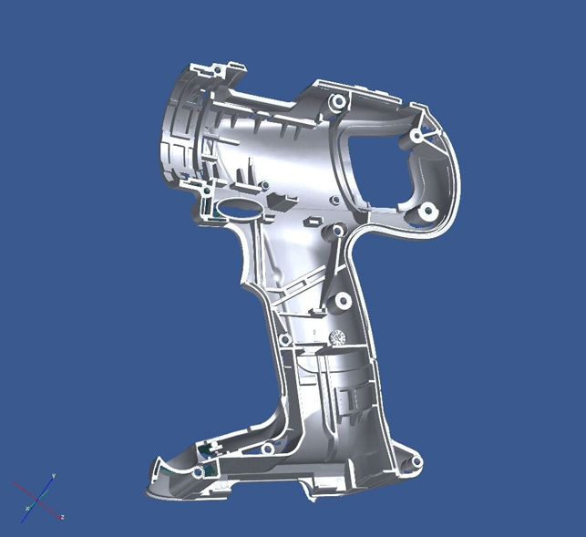
The parting surface of the drill casing is the reference for the production, also used to define the dimensions of the part. It is the preferred measuring base for the CMM. Interestingly, the actual surface is not planar and is therefore an annoyance for the CMM operator as, depending on the selected support points, different measuring values are given by the CMM.
To get a first estimate of the actual form and the deviation of the part, the digitized data can be registered into the CAD data using a “best fit” approach.
Then the digitized data can be registered into the CAD data using adequate registration procedures to fully understand the local deviations.
The digitized data is not modified, but the colour-coding and the calculated deviations are adapted to the actual registration and allow therefore understanding and visualising specific effects.
If the reported deviation is understood regarding the functionality and quality of the part, numeric values can be extracted to derive corrected dimensional values and information for the tooling manufacturer. These values can be gathered using data evaluation and quality control software.
For simple parts and deep holes a CMM can usually do a good job. For free form surfaces and complicated parts, the digitiser is far more efficient.
For the periodic test of both systems, it is recommended to measure from time to time a part with the CMM and a digitizer and combine and compare the results gathered by both systems. Then the digitizer and the CMM can be verified and base lined on the same standards.
An increasing number of companies are incorporating dense data digitising systems into their quality and inspection processes. In doing so it is not always to achieve better measurement accuracy, but to bring the measuring processes and techniques in tighter with production and aid in reducing the needed investment to maintain or enhance the quality of their products.
www.gom.com
www.physicaldigital.com
Digitizers facilitate article inspection processes and enhance quality control
No


