

The rapid development of modern 3D CAD systems has facilitated the evolution of product design, and as a result, a move to more organic forms and ever increasing geometry complexity. Just think about the change in design from the conventional box shaped vacuum cleaner to the modern Dyson. The aim of this article is to focus on design fundamentals and the impact they have on the manufacturing and production processes.
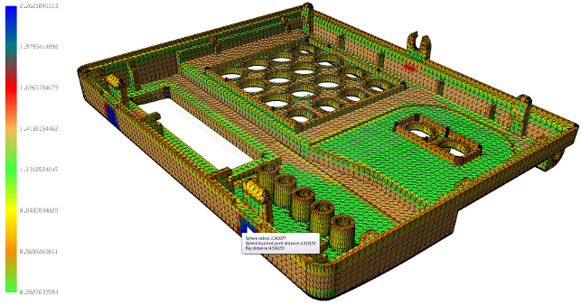
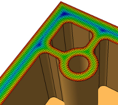
Part thickness analysis will enable designers to identify potential model problems and move more quickly to prototyping and production
Consistent Wall Thickness
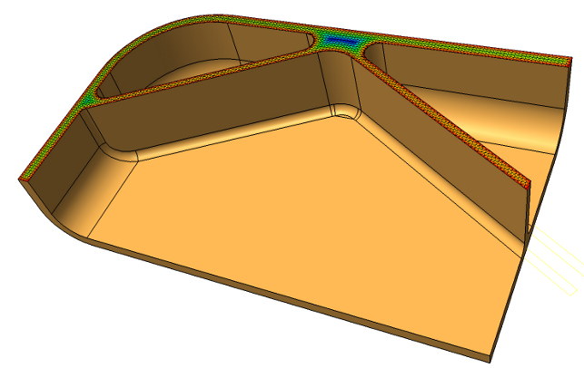
Design engineers need to try and maintain a consistent wall thickness throughout the entire model. Any major change in part thickness can cause major moulding issues such internal voids, surface sink marks, unpredictable shrink rates and ultimately, longer cycle times. If a wall thickness change is necessary, it should be a smooth transition to ensure ease of material flow preventing critical stress points which may cause part failure during product testing and result in an updated part design or additional tooling costs. Detecting manufacturability issues at the design stage will prevent costly
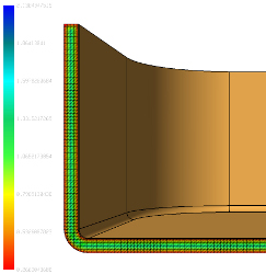
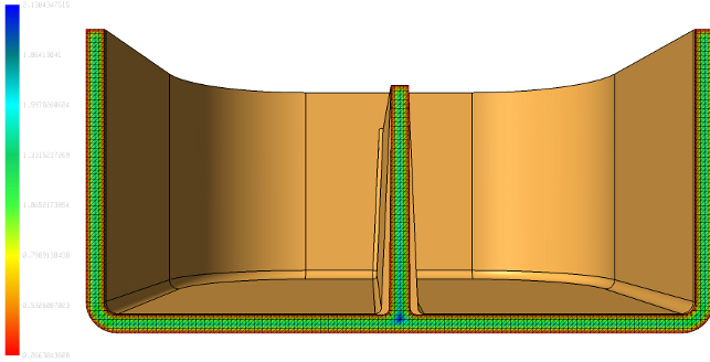
The effect on part thickness when draft is added over the total length of a rib is clearly visible
Rib Design
When creating rib patterns, it is important to remember that ribs are there to increase part rigidity and should not be compromised for aesthetical reasons. Design engineers typically follow standard guidelines for rib design. If possible, a combination of thin and thick ribs should be avoided. Some of the most common design guidelines are listed below:
• Rib thickness should be 60% – 80% of the nominal wall thickness.
• Maximum rib height should not exceed 3 x the nominal wall thickness. To increase product rigidity, it is better to increase the number of ribs rather than the rib height.
• Minimum spacing between ribs should be 2 x the nominal wall thickness.
• Fillet radii applied to ribs should be no greater than 50% of the rib thickness.
• Extra thick ribs should be cored out.
• Cross ribbed patterns are preferred (if the design allows) as they offer greater loading permutations and ensure uniform stress distribution.
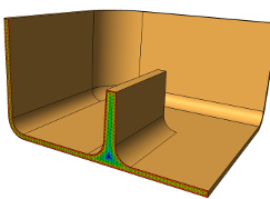
Rib design: excess material accumulation may lead to voids or sink marks
Bosses
Bosses are a fundamental component in plastic part design as they offer strengthening properties and provide alignment during assembly. Similar to rib design, it is important to consider the wall thickness when designing bosses. The design guidelines listed below will help avoid surface imperfections such as internal voids, surface sink marks and unpredictable shrink rates.
• The boss thickness should be 60% of the nominal wall thickness. If the part thickness is greater than 4mm, the boss thickness can be reduced to 40% of the nominal wall thickness.
• The boss height should not exceed 2.5 x the diameter of the hole in the boss.
• Corner bosses integral to side walls will result in excess material accumulation.
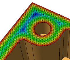
Corner bosses integral to side walls will result in excess material accumulation
Fillet radii should be applied at the base of a rib or boss to allow better stress distribution. If no fillets are applied, high stress concentrations peaks occur and this will often lead to cracking and part failure. Please note however, that if the fillet radii applied are too large, excess material accumulation can occur which may lead to voids or sink marks during the moulding cycle. This same principle is also true where a rib or boss meets the edge of the component.
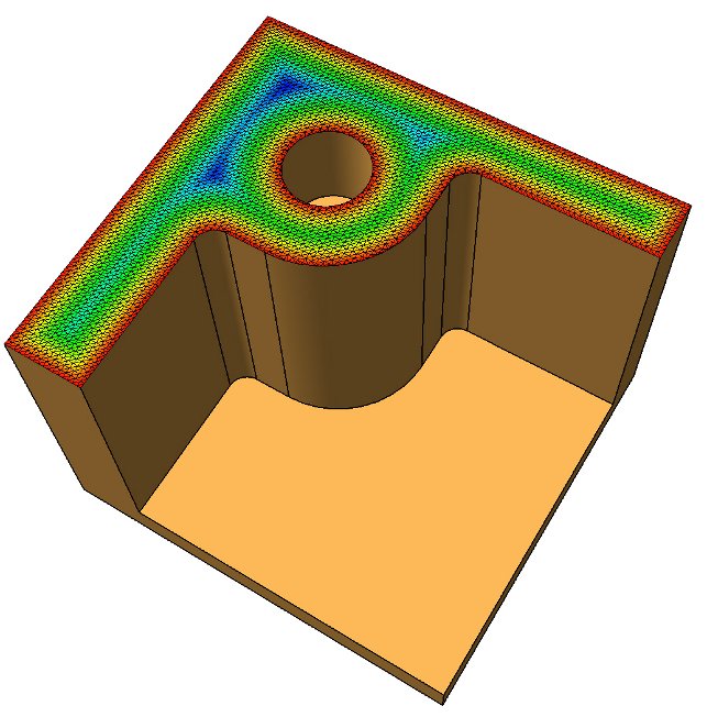
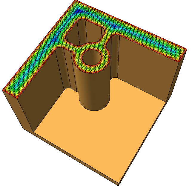
Fortunately, CAD systems are beginning to introduce analysis tools to calculate and display the thickness of a CAD model and help identify potential problem zones.
Corner bosses with orthogonal flanges are a preferred corner design
Typically, two methods are available. The first is based on the largest sphere that can be placed within the model without intersecting any other face. The second is the more traditional shooting ray method which shoots a ray through the model along the surface normal until it hits a second face.
Draft Angle
The need to add draft angle to a model is well understood, but often ignored during the design stage. While this may seem like a trivial task, if the taper is not added at the right point within the history
tree (if applicable) or complex fillets are subsequently added, this task becomes a great deal more complex.
Draft angle is an important feature that allows a moulded part to be extracted from a mould cavity without issue. The high pressures of injection moulding and material contraction means that it is often difficult to remove the part. While it is possible to mould parts with zero draft (or even negative draft) using side cores, lifters or two-stage ejection, these features dramatically influence the complexity and cost of the tool.
Draft angle analysis will enable designers to identify potential moulding issues prior to core and cavity construction
Although no exact formula exists for defining the correct draft angle for a certain part, there are many factors that have an impact on the optimum value. Generally, thin-walled parts that undergo high-pressure injection moulding need more draft as the material is forced in which results in a tighter grip on the cavity. Equally, parts that are subjected to lower-pressure moulding can have less draft.
For smooth surfaces, generally a minimum of 0.5 degree draft per side is recommended although experience has shown that a draft angle of one degree per side provides easy ejection for most surfaces.
Textured surfaces are slightly different as the non uniform texture will drag and scuff, ruining the required effect if the draft angle is not sufficient. As a general guideline, a minimum of 1.5 degrees per .025mm depth of texture needs to be allowed for in addition to the normal draft amount.
The depth of draw (deep ribs) is a very important consideration because as the distance of draft becomes greater, ejection becomes easier but the thickness of the geometry also becomes thicker, and, as we have already learnt, dramatic changes in model thickness may cause internal voids, surface sink marks and unpredictable warpage. As an example, a draft angle of one degree over a drop of 100mm would increase part thickness by 1.75mm per side.
Although at the product design stage, the moulding polymer may not be known, this can have an effect on the required draft angle. For example, materials with fillers (glass filled) tend to have a reduced
shrinkage value and will therefore not move away from the cavity wall. In this case, greater draft angles are required.
Holes are easy to produce in moulded parts and are typically created using core pins. However, blind holes with zero draft often create a vacuum effect at the top of the core pin during ejection (more prone in parts with a polished finish). In this case, a small draft angle will break the seal and improve ejection. Ultimately, the easier it is to remove the part from the mould, the fewer the number of ejector pins required.
Part Radii
A significant number of plastic parts fail due to sharp corners or insufficient radius. Sharp corners create localised stress concentrations which will promote crack initiation and cause premature part failure. The addition of fillet radii to all sharp corners will not only reduce stresses, but also improve plastic flow.
As a general rule, at corners, the inside radius is 0.5 x material thickness and the outside radius should be 1 x material thickness plus the part thickness – a larger radius should be used if the part design allows it.
Mould Tool Design – Gate Position
It is often preferred to gate onto the thickest section of the component to reduce the possibility of sinking due to insufficient material packing. Fixing the gate location ultimately determines the filling behaviour, weld lines, shrinkage, warpage and surface quality of the moulded part. Weld lines are lines where two plastic flow fronts meet and form a relatively weak bond. These are the areas most likely to fail when the part is under stress.
In the engineering world, for a project to be successful, it is a continual compromise between product design and production feasibility
Complex mouldings will always contain weld lines and if the number cannot be reduced, they should be moved to noncritical areas of the component. This is typically achieved by moving the gate location or if the design allows, changing the part wall thickness.
Conclusion
We have briefly studied six plastic product design principles. While each of the points are generic and cannot be applied to every scenario, they are certainly a solid base from where to start your next design. So, next time you shell out a model or drop in some strengthening ribs, don’t forget to consider the impact these decisions have on the production cycle.
In the engineering world, for a project to be successful, it is a continual compromise between product design and production feasibility.
www.vero-software.com
Complex, organic forms are a hallmark of modern plastic products, writes Marc Freebrey


