Since the dawn of the Computer Aided Design (CAD) industry there’s been talk of how it will kill off the engineering drawing.
But as we all know, the engineering drawing, as a means of documenting, annotating and distributing information that is critical to the production of parts and products, has gone nowhere.
CAD-derived engineering drawings have changed a lot since the early days and over the last few years we have seen the introduction of 3D annotation techniques.

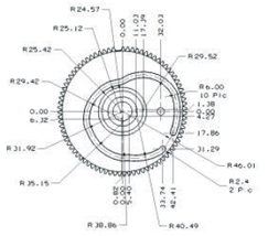
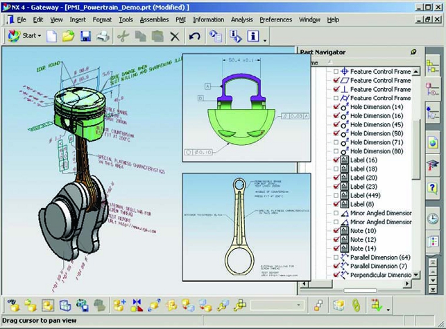
Fig.1 – A dimension-heavy part view created using traditional methods
This combines the geometric accuracy and unambiguous nature of 3D models with standard and established methods of documenting factors such as dimensions, tolerances, assembly information and other critical information — all within a three dimensional product model.
One organisation that has been leading the charge for 3D annotation is Siemens PLM Software. The focal point for its efforts is Product and Manufacturing Information (or PMI for short) which has been integrated into the core of its products over the last decade or so.
Beginning with I-deas and Unigraphics, more recently tools to both author and reuse PMI data have been integrated into NX, Teamcenter, Tecnomatix and other applications. So let’s explore how this works, how the data is shared, what it can mean for both the authoring parties and those reusing PMI throughout the digital design to production process and beyond. And then where things are headed.
The basics
Siemens’ definition of Product and Manufacturing Information (PMI) is as follows:
“It is used in 3D CAD and/or collaborative product development systems to convey information about the design of a product’s components for manufacturing.” To add a little more detail, it “conveys information such as geometric dimensioning and tolerancing (GD&T), 3D annotation (text), surface finish and material specifications.”
For those that haven’t looked into this technology (and it’s also available in some form in almost every other 3D design system), it allows you to take the GD&T you would normally reserve for a drawing sheet and attach them to the geometric model.
One important point to note is that 3D annotations, as defined in a number of standards we’ll discuss later on, aren’t just thrown at the model, but rather added in a structured manner — much as you would in a traditional 2D drawing.
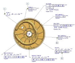
Fig. 2 – The same component with PMI added, featuring clearer annotations and more information
Views are defined, the dimensions and other annotations are attached to that view and made available for the viewer — ensuring that clarity is maintained.
Take the example shown in figures 1 and 2. The centre line for this cam trace would take considerable effort to define and document correctly using a traditional drawing approach (figure 1 shows just the geometric dimensions). By using PMIbased on a 3D model (shown in figure 2), the geometry of the part is already defined and can be extracted by the machinist for manfuacturing.
The critical tolerancing information is that which is added to the model and, according to the automotive supplier who provided the data, the use of PMI in this instance reduced the time required to tolerance this component by between 50 and 75%.
Delivery & collaboration
Within the scope of Siemens’ product range, PMI is becoming pervasive, both in terms of authoring tools such as NX and Solid Edge, but also within other areas, such as production preparation.
NX has a full set of definition and adaptation tools that allow the creation of the PMI. Annotations are associatively linked to faces and other references and the user interface allows organisation of PMI using the standard part navigator.
In earlier incarnations, NX focused on the creation of dimensions and tolerances, but this was expanded to include all manner of other information. This ranges from general notes, through to enterprise identification, material specs, part IDs, process specification, even hyperlinked information.

Essentially if you want to add the annotation to the part model, you can. There are even security-related annotation tools that require the user to accept specific terms and conditions before they’re even allowed to interact with the PMI.
No discussion of PMI is complete without reference to the JT format. While having started out as a proprietary format, JT has become an ISO ratified standard that allows the sharing of not only geometric data, but also PMI information.
PMI and JT are becoming inextricably linked, both as the standard documentation visualisation method within Teamcenter and with supply chains at large across many industries (although the automotive industry remains the largest adopting industry sector).
Downstream data reuse
The potential for reusing PMI data is huge and Siemens has been working on this aspect quite heavily over the last release cycle or two.
Yes, the data can be very quickly extracted from the 3D model and presented in more traditional drawing sheets, but the potential is much larger.
PMI holds many benefits for those in manufacturing and production. In terms of machining, there are moves to drive the creation of NC toolpaths from PMI data. The current release sees NX CAM analyse any PMI data within a part model file and reuse it as input into feature-based machining tools.
These values can drive the selection of machining operations and the associated tools — of course this depends on how you have set up your system. There are a couple of benefits.
While feature-based machining is traditionally very good at detecting design changes, with a PMI-based approach, it’s possible to have toolpaths that also adapt to changes in tolerances, surface finish and such.
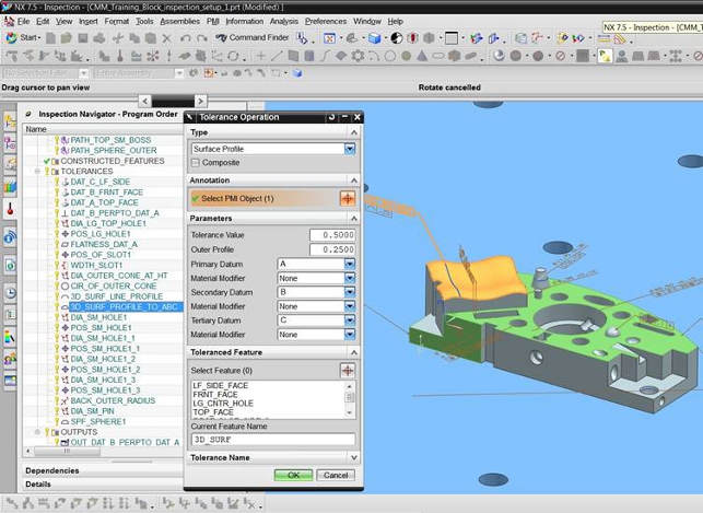
Another area of production in which PMI can play a huge role is inspection and metrology. With the NX 7.5 release cycle, it introduced the CMM Inspection Programming module. While this is general purpose in terms of programming numerically controlled Co-ordinate Measuring Machines (CMM), it does contain one small function with huge potential for PMI adopters — the Link PMI button.
This uses the 3D part geometry and attached PMI, extracts all of the identified features and tolerances and creates all the inspection operations necessary to inspect the part. The movement and inspection routine for the CMM is then derived from this and made available.
Conclusion
At the outset, I asked if PMI and 3D annotation is likely to kill off the engineering drawing. I’ll be honest, it was asked with tongue firmly in cheek. Of course it won’t.
The engineering drawing is still the de facto standard for communicating engineering and manufacturing information and will remain so for the foreseeable future — and probably beyond.
But the fact is that technologies such as PMI have the potential to not only make the production of those drawings more efficient, but also add much much more.
By loading the absolutely critical information required to manufacture a component into the 3D model, it can not only drive efficiency in the draughting process, but also make that data available to other downstream process — to anyone that needs it (for example, through the Teamcenter visualisastion tools).
PMI also has backing from professional bodies. ASME, ISO and JEITA are already integrating PMI practices into their standards including ISO 16792 and ASME Y14.41. Siemens PLM is also the vice-chair for the Technical Advisory Group (TAG) to TC-10.
While more vendors are starting to add similar tools into their own products at the moment it looks like Siemens PLM is the one that is leading the path forward, both in terms of making the tools to define PMI more accessible, but also in terms of what can be achieved once that data is there. 
Will Siemens PLM be the death of engineering drawing?
Default