Laurence Marks talks us through contact routines in structural simulation
Contact remains an ongoing challenge in structural simulation. Even though software and hardware development has driven the technology, and its use along, modelling contact is yet to enter the realms of things we once worried about, but don’t any more.
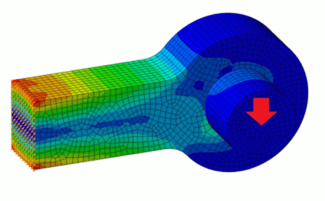
So what do I mean by contact? In finite element analysis (FEA) it has a distinct meaning, and application. In some ways it fulfils many of the functions of assembly mates and definitions in a CAD program, but it does it in a distinctly different, and more physically representative manner.
If we think about a very simple example – a pin in a lug – a number of fundamental concepts are highlighted. In the CAD model we want the pin to sit in the hole in the lug, and the end of the pin to be positioned a set distance from the centre plane of the assembly.
All very simple. However we, as simulation engineers, want to model the physical behaviour of the pin in the lug, and that isn’t “all very simple”.
So what happens? Well, that depends on the interface behaviour.
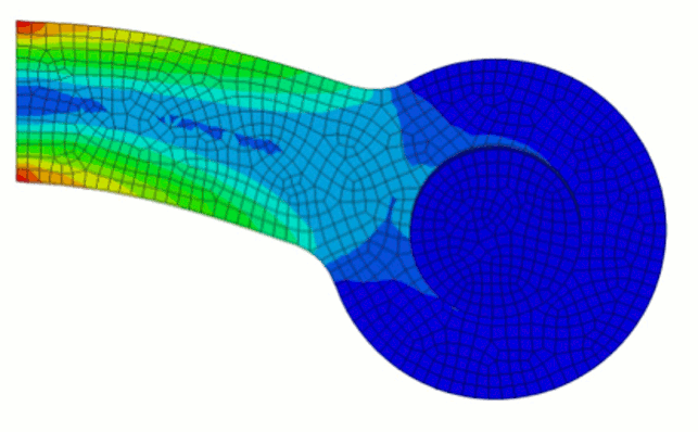
If by some magic production process we manage to perfectly bond the pin into the lug then the finite element model definition is straightforward; all nodes on the surface of the pin are joined to the nodes on the bore of the lug, and any loads pass through the entire interface.
But in most situations the pin just sits in the bore and when we load the pin, some areas of the interface come together and a load passes through them, whilst some areas move apart forming a gap, through which it is obvious that no load can be transferred.
We therefore get a very different solution.
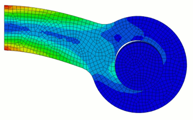
So far so good. But the first point that is evident to the engineer is that the problem solution time has jumped from seconds to minutes, even for this simple test case. That’s assuming you got an answer at all.
The faces of every element on the bore had to work out if they were in contact with every exposed face of every element on the surface of the pin, and from there work out how the force should be shared amongst themselves.
On top of that the system, or the engineer, had to work out how to stop the pin heading off to infinity, or beyond, before this process got going. Hardly surprising, then, that things slow down a bit. It won’t come as a surprise that there’s more.
Friction defines how loads are transmitted across an interface; it’s definitively the resistance to in plane motion as a function of the compressive load across it.
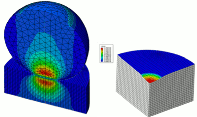
So the finite element representation of an interface can have a friction coefficient applied to it, and then, with even more calculation, the effects of this can be incorporated. But there’s still more; the friction can be slip rate, pressure and temperature dependent,
and any decent FEA solver can incorporate this.
Contact also brings additional data to the post processing party. Contact pressure, gap opening distance, shear forces and more can all be plotted on the surface of the model; all critical design data if wear is a critical aspect of component performance.
Defining contact in modelling systems has been an area where great strides forward have been made.
In the early days the engineer had to define the interaction between nodes individually, almost certainly in a text editor. In later systems, engineers could select areas of geometry to model and track contact behaviour, and in fact this is still the most common way of working.
General contact, is however a new direction of travel, and one which is gaining in popularity. In general contact you simply throw a contact switch – model contact – and the computer literally does the rest; at interfaces in the model all the contact definitions are automatically created and solved.
And where the engineer wants different things to happen, i.e. bonded regions, areas where different friction or other interface behaviours need to apply, he simply applies them as and where needed.
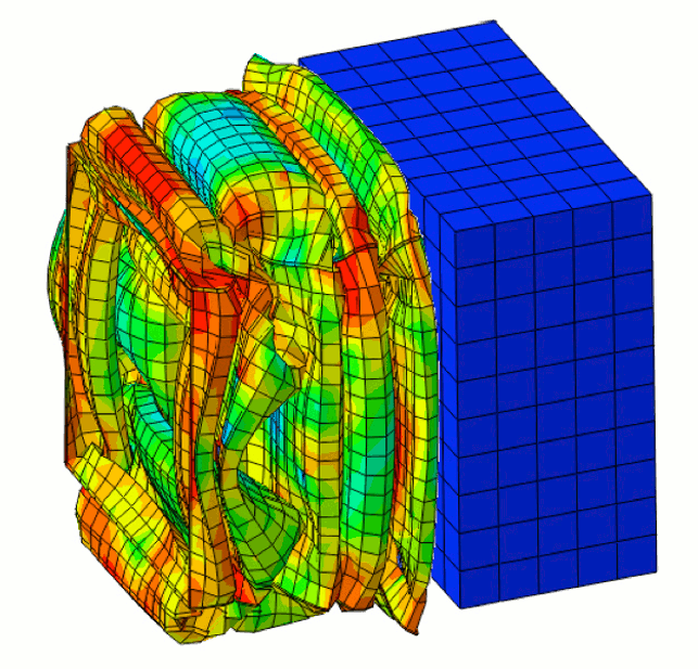
So this process is simple? Well not really: much simpler than it was, but not simple. The calculation overhead of big contact calculations is certainly not trivial, think hours and sometimes days rather than minutes, and the scope for things going wrong is considerable.
This is before we get into concepts like self contact, where the system has to track a collapsing structure’s tendency to concertina, creating small regions of the surface which come into contact with other regions of the same surface.
One thing is certain; the effectiveness of the contact routines in a finite element solver have a direct bearing on how far it can become a routine part of the design process.
A designer’s system that needs an expert to set up and trouble shoot every contact definition can’t be rolled out far into the design office.
We’ve come a long way in this challenging area, and in many situations solutions are very reliable, but it’s far from a done deal.


