Siemens’ Solid Edge product has been on the market 18 years now and it has been through a fair few owners, but has always had the same core concept at heart.

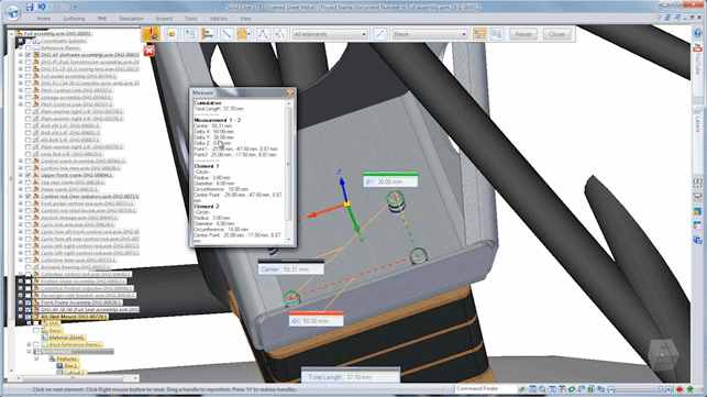
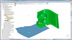
ST7’s measurement enhancements allow you to stack up measurements of and between objects as you need them
To provide a Windows-based system for design and engineering development using 3D CAD as the basis. While the marketing initiatives have come and gone, it’s found a loyal following in the near two decades of its activity.
When Synchronous technology was introduced in 2008, it got a profile boost as it rode on the burgeoning interest in direct editing. While this technology has gradually matured and become better integrated with the traditional history-based modelling tools, Solid Edge is still, perhaps, riding on that increased wave of interest.
So, with each release, it’s interesting to see where things are heading for the mainstream 3D design-focussed system. So let’s take a look.
Generally useful updates
Let’s begin with the updates to this release that are applicable to most users, irrespective of what industry or common workflows they use.
The Solid Edge user interface has been evolving over the last five or six releases and while wholesale changes are now few and far between, there are a few tweaks, enhancements or additions that will make life easier or more productive for existing users (new users will, of course, not notice any difference).
Perhaps one of the most useful of these enhancements is to the measurement tools. While every CAD system includes tools to measure both geometric entities, as well as between them, they’re often not pervasive or indeed, remain on screen while you use them. Solid Edge, until ST7, was also guilty of this.
From ST7 onwards, the measurement tools remain on screen as you use them, giving you greater ability to measure between entities and allowing you to stack up measurements and retain them on screen as you need them.
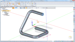
Another update that’s going to be welcome to many, is the ability to create 3D sketches using a wider variety of entities without the need to predefine workplanes and such.
Essentially, you sketch each segment on a dynamic plane, then shift that plane to the next to add in the additional elements in a different direction. It works with both lines and arcs and allows you to create fillets between those entities.
For those working with piping routing, wire or tubular forms, this is going to be manna from heaven. Of course, if you want to include more complex splines that route through points that aren’t co-planar, this can still be done, but using the more complex tools that have been in the system for a good few years.
There are also some enhancements made to the materials definition database that’s available within Solid Edge. This has been revamped and now gives a much richer description for each material and a wide range of materials all together. Interesting, the team has also built in the ability to download and integrate materials from online repositories, such as MatWeb.
Also on the standards front, the hole creation tools have been reworked. Whereas in previous releases you defined the holes and fasteners separately, you now do it much more intelligently. Essentially, the hole creation form now requires the definition of the fastener that’s intended to interface with that hole, and the thread forms are derived from – and it includes all the major international standards including (DIN, ISO and ANSI).
Perhaps the last major update on the generally applicable front is the ability to assign a specific length to a sketch entity (or group thereof). For those working with standardised tubes, pipes, belts and such, this wil be a huge benefit, but I’m sure it’ll find its way into many other users’ lists of command options.
Working with Assemblies Alongside these generally applicable updates (which often apply to both part and assembly modelling), there’s also been a bit of work done on tools that focus on assemblies specifically.
Perhaps the most useful is the ability to duplicate components along a curve. This works similarly to using a sketch to drive a feature part, but with separate parts.
What this means is that it’s possible to take a part (or, indeed, a sub-assembly) and have it patterned along a specified curve (or group of curves).
Imagine a subassembly of a track for an earth moving vehicle or perhaps a complex belt or chain device. Rather than creating multiple instances of each link in that chain, you can duplicate these along the appropriate path and it’ll maintain position and orientation just as the fully mated version would, but without the massive compute overhead that a design change would require.
Another assembly modelling update continues the work done in ST5 and 6 to better support the use of lightweight representations of large and complex assemblies.
Regular readers (and existing Solid Edge users) might recall that this revolved around the shrinkwrap type of tools that are increasingly common. Solid Edge’s implementation allowed an assembly of parts to be replaced with a combination of either a boundary ‘lump’ of geometry that represented the exact form of the assembly, or to swap components out entirely for prismatic forms.
The problem was that while these lightweight forms allowed users to load and inspect an assembly more efficiently, it didn’t carry over any of the BOM and metadata attached to the parts it was representing.
This release changes this and now it’s possible to extract this type of information (for BOM lists as well as in drawing tables) without having to load the fuller, complete representation.
The final major update relating to assemblies for ST7 is in the area of change management. While Solid Edge has (as we’ll explore shortly) data management tools available using SharePoint or Teamcenter as the basis, change management in groups without formalised data management is still an issue.
The new tools allow users to track when parts or sub-assemblies (either above or below the level you’re working at) are changed and might kick off a complete rebuild of the model.
These new tools allow you to find these instances (on loading a model or moving your focus within the assembly) and to selectively choose whether the assembly is updated and refresh.
Sync Tech updates
No Solid Edge release is complete without a quick rip through some of the enhancements made to Synchronous technology. It’s been a good few years since Sync Tech was introduced into the system (six, in fact, I think) and while the days of massive updates are gone, there is a constant refinement of the tools to make them more intelligent and allow the user to work more efficiently.
Big ticket items for this release include the ability to find feature patterns within other patterns, so that the user has the ability to adapt them where needs be, whether the upper level pattern or each individual pattern within it.
Elsewhere, the system also now allows you to create primitives, specifically, boxes, cylinders and spheres. It’s this type of operation that you could, of course, carry out with a number of operations in previous releases, but these new tools are much quicker to use. Drag, drop, pull and pull into shape and you’re done.
The last highlight on the sync tech front is some work done on chamfer recognition. As ever, the use of both chamgers and fillets using direct editing is problematic, particularly when you get into the more complex examples.
It allows you to identify the edges/faces that are chamfers (or not, as the case may be) in advance, then allows the editing of feature names, any set-back dimensions and such.
Sheet metal
Now then, sheet metal is an area that Solid Edge has always had a strong presence in, right from the early days. It had intelligent sheet metal tools long before many of its current peers in the mainstream modelling market. As ever, its no good resting on collective laurels and this release sees work done to refresh the sheet metal modelling and editing tools in the system.
Strangely, the first is something that other systems have had for some time, namely, the ability to create the exterior form of a sheet metal component using a solid model, then convert it to a sheet metal fabricated form.
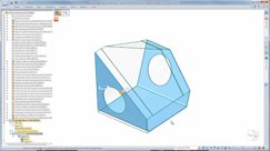
The tools are nice and simple, the Part to Sheet Metal operation takes care of the whole process, allowing you to define material parameters (in terms of bend radius, corner treatment etc.) then identify the base (for the first section of sheet).
You then work around the model, first selecting edges that are converted to bends, then by hitting the R key, select any edges that are ‘ripped’ – those that open up and enable the flattening of the form. You can see the full workflow on the opposite page for more details.
Once done, you have an intelligent sheet metal model that links back to the source solid (so any changes can be propogated quickly) and one that can also be converted into a flattened form and pushed into fabrication and into drawings for documentation.
The last sheet metal update relates to deriving flattened forms from non-sheet metal forms. Essentially, this allows you to take a constant wall thickness part (whether natively built or imported) and flatten it out according to a few input parameters.
The end result is a 2D shape that, while perhaps a little rough around the edges, can be used for initial nesting planning for all manner of purposes, whether that’s fabric work or stamped forms. This, of course, also ties in rather nicely with the forming tools from ST6 that allow you to ‘push’ a form tool into a thin part and create these types of stamped or forged parts more easily using standard solid modelling operations.
Visualisation with Keyshot
Solid Edge has had integrated rendering tools for the last 10 years or so. Based on the Lightworks engine, it has followed the usual route of being slightly overly complicated (a side effect of being in a user interface built for design work, rather than visualisation) – a problem that’s common in almost every 3D design system at the moment.
For the ST7 release, this changes. The existing tools are still there, but from now on, it looks like Siemens will be offering users access to KeyShot from Luxion.
Most DEVELOP3D readers will be familiar with KeyShot – it rewrote the rulebook on how easy rendering and animation should be, by using a drag and drop approach rather than twiddling of values and complex dialog boxes.
If you’re a Solid Edge Classic or Premium customer, you’ll now have access to KeyShot for Solid Edge. This puts a couple of icons into Solid Edge that allow you to send the current data directly to KeyShot for rendering. Of course, using KeyShot’s LiveLinking technology it’ll maintain that link, so updates can be propagated as designs evolve.
KeyShot for Solid Edge gives you real-time rendering (at 2.1 megapixel resolution – equivalent to 1920 x 1080) and offline, fully calculated rendering to any resolution you want. It’ll try to maintain any material assignments from Solid Edge. It doesn’t come with the animation tools in KeyShot Pro but it can be used to render out frames defined in Solid Edge’s native animation tools.
There are a couple of things worth noting. The first is that KeyShot has to be installed on the same workstation and is tied to the Solid Edge license. The second is that despite, the tied license, if there’s an update to KeyShot, you can get it and update your version.
Another factor worthy of mention is that your bundled license of KeyShot doesn’t include importers for other files. The data has to be transferred via the integration with Solid Edge. Finally, if you’ve already got KeyShot in-house, it does give you the benefit of an additional license and the KeyShot native BIP files can be read between the two.
Draughting & Drawings
To round things out, let’s talk about two areas that while, they’re not the most exciting, are just as important as all the flashy modelling tools discussed elsewhere in this release.
The first is drawings and no 3D CAD release is complete without at least a few new drawing tools or enhancements to existing ones.
For ST7, the highlights are in a couple of areas. Firstly, there are new fully automated tools for placing and adjusting co-ordinate dimensions using the fence select that automatically repositions the series of dimensions and spaces them rather nicely.
Another relates to documentation and GD&T, specifically, the use of reference frames and datums. The new release makes these types of references associative, so if you change the datum reference, it’ll also update the control frame to reflect the new alphanumeric text.
The last two relate to the placing of drawing views into your sheets. Firstly, there are improvements to the display of each view – instead of a bounding box, you now get a full preview showing the view as it’ll appear when placed. The second is that within multi-sheet drawings, you can pull in sub-assemblies or other parts from the assembly and document them – enabling you to keep all of the documentation relating to an assembly in a single place – making management much easier.
Data management
Let’s wrap this up with a look at what’s changed for data management. You may recall that Solid Edge’s SharePoint-based data management solution (Solid Edge SP) was introduced in the last release.
This builds on a standard SharePoint implementation to add in not only a greater understanding and support for the complex data links between parts, assemblies and drawings, but also the complex workflows that are common in engineering and production.
For this release, Solid Edge SP gets a face lift, particularly in the area of visualising your data, particularly in the Relationship browser tool that displays the hierarchy of your assemblies graphically.
You can now show multiple property cards, which display the meta data associated with the selected parts. While present in the last release, you were limited to a single card at a time – no more!
The other major update is that while it’s entirely possible to create formalised workflows, sometimes you need something more ad-hoc.
This is now possible and you can quickly create a workflow to push a task through your process and team without too much pre-amble.
Conclusion
I think that’s a pretty good overview of what’s new, updated and improved in Solid Edge ST7. What’s interesting is how the development is looking back at existing tools and finding new ways to make them more efficient. A good example is the work done on some of the core modelling techniques – whether that’s 3D sketching, working with sheet metal forms or the additions to the sync tech tools.
Elsewhere, the team has also looked at some areas and completely revamped them. The prime example is in the rendering field.
While you could produce half decent renderings in Solid Edge VirtualStudio, like all CAD integrated rendering tools, it’s complex and heavy.
The link up with KeyShot is a good move and while it’s reserved for those with the Classic and Premium bundles, it’s a good deal and one that should prove useful for many.
After all, rendering is no longer the sole preserve of the industrial design crowd and is a common part of designers’ and engineers’ workflow, in a much wider spread of industries.
All in all, ST7 shows how Solid Edge continues to evolve and mature and that’s what many users are looking for.
A solid, reliable tool to assist with not only building and documenting their design and engineering work, but also one that has links to other workflows and requirements that are part of the process, whether that’s simulation (which we’ve not covered), visualisation or manufacturing specific readiness.
siemens.com/solidedge
| Product | Solid Edge ST7 |
|---|---|
| Company name | Siemens PLM Solution |
| Price | On application |

