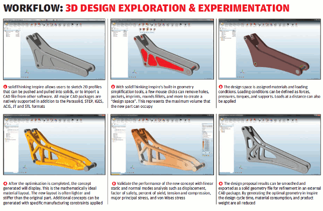
SolidThinking Inspire has been on the market for a good few years.
It offers an easy to use environment for designers and engineers to take advantage of FEA-driven optimisation to find new avenues for design exploration, without the overhead of traditional simulation systems.
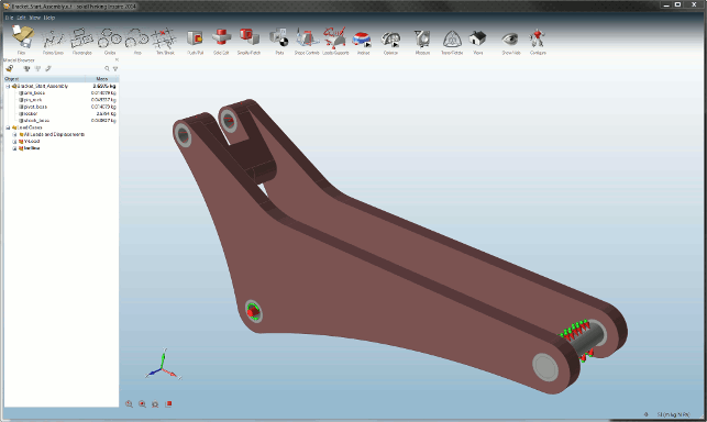
Inspire has both basic solid modelling tools as well as rich import options and a new set of tools for modelling
It does this by hiding much of the technology behind a very easy to use interface that allows you to build models and studies quickly and iterate through options to find inspiration for your design direction — hence, presumably, the name.
Inspire works on the basis of using a varying set of geometry. These are typically either modelled from scratch or imported from a CAD system.
It’ll load data in the usual standard formats, such as IGES and STEP, but also Catia, JT, Parasolid, Pro/Engineer or Creo, SolidWorks and NX. Once the data is in, then you need to start to work with it.
Previous releases of Inspire have done a good job of bringing data in from your CAD system or letting you model basic forms from scratch.
The issue has always been that while the ‘from scratch’ modelling tools were perfect for just that, if your imported geometry wasn’t exactly what you needed, there wasn’t too much support for making quick edits to knock it into shape. This has been a particular focus for the 2014 release.
In the first and most basic instance, this means that you have the now familiar tools for pushing and pulling faces of solid geometry into the position you want — select the face, drag the handles and you’re done. There are also tools for cleaning up solid geometry.
From selecting faces and deleting them, to identification of pockets and such. These are ideal when you’ve got a specific set of geometry you want to optimise. The goal here being that you’re looking to reduce the mass of a component, but only have areas that can be changed or reworked.
This allows you to grab geometry (such as cut outs in spar like components) and use those as separate design spaces for optimisation, which we’ll explore next.
Setup & design spaces
One of the most powerful capabilities in Inspire is the ability to split up a model into geometry that needs to be retained and that which is open to be optimised — these are referred to as a Design Spaces.
An understanding of multi-body modelling processes will be an advantage here, as it’s the perfect way of defining these Design Spaces — either in your CAD system and importing them or building them from scratch (the former is perhaps, for complex forms, the most efficient).
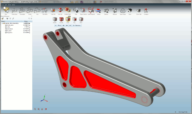
Inspire’s new tools allow you to take imported solid geometry and make adaptations and edits where needed
Whichever method, once you have them in the Inspire session, you can define them as such, which is a quick right click and selection of the “Design Space option.
This will flag them up in the UI in a maroon colour, so you know what’s what. Once done, it’s time to define the characteristics of the study.
It’s good form to define a material. The system comes with a shortlist of most common engineering materials, such as steels, aluminiums, titaniums and a couple of plastics options.
These give the system a steer when running through the optimisation, but this is by no means essential.
Next up is the definition of the boundary conditions. Loads and constraints are pretty obvious. As with most Inspire commands and operations, these are selected from the row of icons across the top of the screen.
These are worth studying in some depth as each has multiple uses and gives you access to a number of operations. For example, the constraints icon not only has constraints, but also, depending on which part of the icon you select, lets you apply forces, torques and pressures.
Another area to pay attention to is the symmetry and design for manufacturing constraints.
These allow you to define standard planes of symmetry as well as defining conditions that will steer the results towards an outcome that’s suited for machining, for stamping or moulding.
Analysis & optimisation
The optimisation process has changed a little in the latest release with 2014 seeing a quick analysis tool introduced into the system.
This rips through a standard linear static analysis of your model and gives you a quick set of results based on your load cases (it’ll solve all of them at once if you need it to).
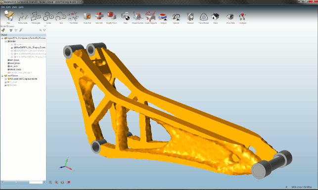
How the final results can look, with a mathematically optimised shape. This can then be further refined using additional studies
These can be filtered by result type and all the usual values can be plotted on the model, such as maximum principal stress, shear, displacement and the like. There’s a filter tool in the legend key, so that you can quickly find areas of stress/strain concentration and see how it progresses through the model.
The purpose of this is two fold, as far as I can see. Firstly, it gives you a sanity check on your model to make sure it’s in line with your expectations.
The second is that it’s perfect for demonstrating how the optimisation process works and gives you some idea as to why you end up with the results you do (it can throw up some novel results that you might not expect). There’s also another use, but we’ll get onto that shortly.
The next step is to then kick off your first optimisation study. You define the parameters for that optimisation (such as maximising stiffness or minimising mass).
You can have this work to a specific factor of safety, incorporate natural frequencies and define a minimum thickness constraint.
Progress your design
Once your study is done, the results become available for inspection (look out for the small flag popping up on the optimisation icon).
Opening these, you’re given a list of results sets to work with. One of which will show you the resultant shape.
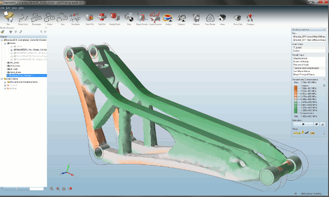
The new simulation tools let you run a quick analysis of the final forms, so you can see how it performed under the loading conditions used to perform the optimisation originally
You have a topology slider so that you can transition between the original and final form — this allows you to see how the mesh decimates to the final form.
There are also shading tools to help plot various factors such as factor of safety, principle stresses, strain etc.
In previous releases, this would be where your workflow would end.
You’d take this final mesh form, create a report if need be and then use it as the basis for complete rework in your workhorse design system, using it as a reference for creating a more analytic solid model.
While that hasn’t changed, there are a few additional tools to support this. The issue is that most 3D design systems don’t allow you to do much work with mesh data.
Recognising this, the solidThinking team has built in a smoothing algorithm that will smooth out any issues in your mesh and allow you to output more standard CAD geometry as a STEP file, as well as a few other formats. This makes the loading of result data much easier and allows you to work with it .
While for traditional manufacturing processes, the complete rework makes the most sense, if you’re working with additive manufacturing techniques, chances are you’ll be able to work with the data as is, with very little additional work.
Then, of course, you can run this data back through the simulation tools we discussed earlier to see how it performs and validate your results, before you progress it further.
As you’d expect, this is a pretty straightforward process as you’ve typically already defined the loads and constraints when you initially set-up the study in the first place.
Conclusion
We’ve looked at solidThinking Inspire pretty consistently since it was released some years ago.
What’s been interesting to watch is, while the basic premise of the system hasn’t changed, the tools available in it have matured to support that premise.
The system is all about exploring design potential and finding areas of inspiration for your work.
Its goal is not a final clean cut analytic model, rather to take the various inputs and requirements of a product’s performance, combining it with shape optimisation and finding new, innovative ideas and directions for further work.
The issue has always been that the end result of the optimisation process didn’t fit into a neat workflow for progressing those new ideas further.
The result, in previous releases, was a mesh, which as most of you will know, isn’t all that useful when it comes to reworking in your main CAD system.
Most don’t even allow you to take measurements from such forms, never mind create references to it.
This release allows you to now create much more usable forms that can, if needs be, progressed into more formal design iterations and workflows.
Combined with the new built-in analysis tools, the system, in my opinion, is much more usable than ever before.
| Product | solidThinking Inspire 2014 |
|---|---|
| Company name | Altair |
| Price | on application |


