Solid Edge has been on the market for almost two decades now. While for many years, it was seen as a runner-up in the battle for the mainstream design and engineering market, the advent of Siemens’ synchronous technology eight years ago won the software a lot more exposure.
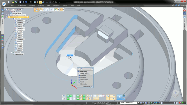
The new Design Intent panel pops up to give you live feedback on relationships found, based on your selection and surrounding geometry
Since then, the company has adapted both the delivery and implementation of the software and the messaging that surrounds it.
Today’s reality is that while Solid Edge still has all of the power of its traditional modelling tools (which use the history-based approach), these are now supplemented by a set of hyper-intelligent direct modelling tools that give the user a less structured but more efficient way to create, edit and adapt geometry.
It’s not a case of using one or the other, but of choosing the best approach for the process or task at hand.
At the same time, the system has continued to mature in almost every other respect, from data management with its SharePoint-based Solid Edge design management solution, through drawing generation, simulation and analysis, as well as elsewhere.
So let’s take a look at what Siemens PLM has in store for Solid Edge ST8.
Synchronous technology
The first area of work we’re going to look at on the synchronous technology front is how the system handles patterns.
While in previous releases, the system could work with these, it mainly focused on holes and regular patterns. The new pattern recognition and editing tools now work across not only linear patterns, but also polar arrays and patterns driven by tables.
Each is worth a quick look.
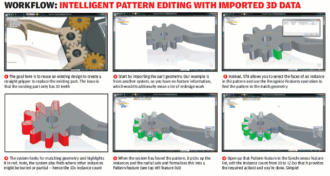
In our workflow below, we’ve detailed how the tools work with radial patterns. The idea is that you select the geometry that represents one instance in an existing pattern (in this case, a tooth on a gear form) and then use the ‘recognise pattern’ operation.
This will find instances that match their axis of revolution and give you an instance count (note that it’ll also pick up partial instances, as found in this use case).
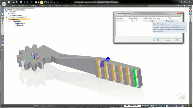
Feature recognition allows you to find similar instances compared to a specific selection
It then adds that pattern into your synchronous feature tree, so you can dive in and edit that instance count and get back to work. It’s simple — and the same workflow pretty much applies for linear patterns as well (as shown in the above image).
The smart part is that you’re prequalifying the patterned geometry, rather than just letting the system do all the work, so you get the geometry you want in the pattern first off.
Another area that’s also been worked on is the patterning of features using nonstandard or uniform methods.
While the system already includes linear, radial and fill patterns, these are supplemented with the ability to drive a pattern by a table.
You first need to create or identify a base feature to pattern, then use the ‘pattern by table’ operation. This extracts the data to an Excel spreadsheet, where you can quickly make edits to each instance’s X and Y coordinates, as well as an orientation angle value (note here that positive values indicate a counterclockwise rotate).
Save that spreadsheet and the Solid Edge model instantly updates.
It’s smart and could be done using builtin tools instead of a spreadsheet — but the benefit is, of course, that you have all those calculation tools inside Excel, should you need to add some additional automation intelligence.
Design intent
One of the key foundations of Siemens’ synchronous technology has been Live Rules.
It’s these that set the company’s tools apart from many of the other direct editing-capable systems out there.
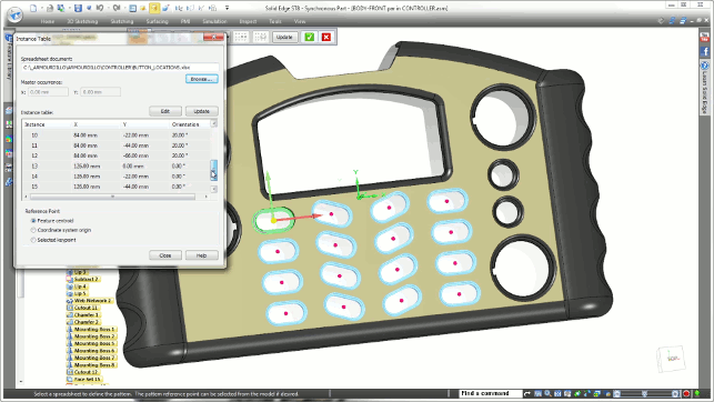
New pattern by table capabilities give you control over position and rotate
Live Rules, if you’re not familiar with them, were introduced as a way to constantly monitor your current selection against your activity (such as move, rotate and so on) and the surrounding geometry, looking for areas where relationships such as parallelism and symmetry could be found.
Live Rules allow users to select one face, find others that might be related to it and make wholesale edits.
Think of the process in these terms: selecting a hole, having the system find similarly aligned holes and moving them all at once. Or, selecting a face in a pocket, having the system find others that are parallel and allowing you to move or rotate them all at once. That’s very powerful stuff indeed.
The issue with this functionality has been that those coming from a history- and feature-driven system could find it complex and often confusing. This was not a fault of the technology per se, but rather down to the prior training and experience of the individual user.
As we all know, if you use 3D design tools day in, day out, you develop ‘muscle memories’ for certain actions and your brain starts to build a set of expectations for certain activities. As a result, Live Rules, while powerful, was overlooked or ruled out by many users.
Siemens has recognised this and, in ST8, reworked how these tools work. This should provide a much easier path for those coming from other systems (and indeed, those experienced mostly in the ordered parts of Solid Edge).
This reworking effort manifests itself in a Design Intent panel that pops up as the user makes edits using the synchronous tools. The panel shows any potential relationships found, highlights the implied geometry and lets the user toggle certain relationships on and off.
It’s dynamic, it’s intelligent and gives the user much faster control over their direct geometry edits.
Assembly and digital mock up
The last two or three releases saw a great deal of work done to add in more intelligent tools (such as building product structures before adding geometry, for example).
This release continues that work and makes it more flexible, particularly for those working in a top-down design environment.
One such tool (which I wish every other vendor would implement immediately) solves the familiar problem of being presented with a directory full of parts, sub-assemblies and assembly files.
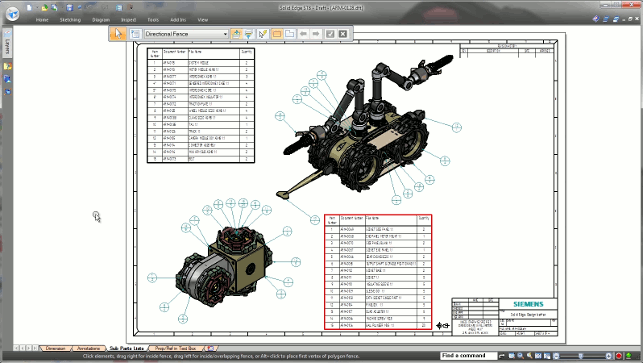
Multiple assemblies on a single sheet – with separate parts lists for each
You’ll no doubt be familiar with the problem of trying to find a top-level assembly among 250 different data files. Unless those files have been named sensibly, this can be quite a chore. Solid Edge now lets you find the top-level assemblies in a directory immediately, by looking for assembly files with no parent associations and filtering to just those ones. Such a simple thing, but a real timesaver.
In a similar vein, Siemens has also introduced recursive searching for those part files that are inevitably missing, so that they’re easier to locate if they get moved accidentally.
Moving on to other assembly modelling updates, there’s a couple that are worth exploring in a little more detail. The first is that you can now take a sketch from pretty much anywhere in your assembly and reuse it in your current task.
That’s irrespective of where the sketch is in the assembly hierarchy, which is perfect for making sure components fit together. It’s a valuable extension of tools introduced in the last release that let you reference 3D geometry in a similar way.
There has also been some work done to make the creation of realistic assembly movement simulation more efficient.
These features allow you to grab drive variables in an assembly and add interrelations to the various constituent parts. This data can then be used in kinematic analysis, for example, as well as to generate accurate animations of your product in motion.
Part level weldments
This is an interesting one, particularly for those working on fabricated components, and specifically, welded forms.
Most 3D design systems include support for the design of piece parts, then use assembly tools to arrange those components and add in the welded forms.
This of course, gives you downstream benefits when you’re working on bills of materials and cut lists, as well as when estimating welding requirements. And of course, drawing generation is included to document the process.
The issue here is that these tools work in an assembly environment and, for some users, that’s not ideal. Solid Edge ST8 introduces the means to do the same work, achieve the same results downstream, but within a part modelling environment.
Drawing enhancements
Now, let’s have a dig into the changes and enhancements made to the draughting portion of Solid Edge.
As ever and as you’d expect, these are well-developed and mature. But that’s not to say that there hasn’t been room to incorporate some new thinking.
The first thing to tackle is the drawing compare tool. This lets you open two revisions of the same document, showing you the two drawings, and then gives you another view that colour-codes where items have moved or changed — perfect for finding small, but vital, design changes.
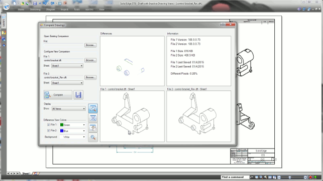
The new Drawing Compare tools allow you to load in two drawings and quickly find areas of change. Particularly useful for complex drawings as well as very subtle design changes
Elsewhere, there’s finer control, not only over how dimensions are placed (with improved snapping), but also in providing a heads-up approach to editing leader lines and such. You just select the leader (or arrow head) and you’re given a small dialog to switch them to the form you want.
Similarly, you can adapt leader lines to the style you want, add in a jog and get it just how you, or your company standards, want it in a very short space of time.
A further enhancement is the introduction of associative call-outs. To my mind, this is a clever and well-executed function that other vendors should look to implement. While the dimensional aspects of a drawing’s annotations are typically associative back to the 3D geometry, the same can’t often be said of the auxiliary text (such as notes, labels and call-outs) that you need in order to complete a drawing.
From ST8 onwards, reference notes can link to works and all notes, labels and call-outs that reference them will update after a change is made.
The final major update is the ability to have multiple assemblies on a single sheet, with their separate parts lists maintained and associatively linked back to the 3D data.
It’s also worth noting that, for some years now, Siemens has been giving away the drawing creation portions of Solid Edge as an AutoCAD (or other 2D drawing tool). That’s certainly worth a look if you’re just after a quick layout tool.
IFC exchange for BIM
It’s seems a little odd to writing the words BIM in an article in DEVELOP3D.
If you’re not familiar with the term, it stands for Building Information Modelling and it’s common in the Architecture, Engineering and Construction space.
Essentially (and probably grossly simplifying things), the construction industry has finally cottoned on to the fact that storing all of the information about a building in an intelligent 3D model might be a good idea. So good, in fact, that the British goverment has made it a legal requirement that any government tenders and subsequent projects are conducted this way. So what does this have to do with a mechanical engineering application like Solid Edge?
The answer is that while the system isn’t used in construction per se, it is heavily used to design and manufacture component parts that go into buildings: HVAC components, for example, or architectural components, such as windows, doors and lifts.
In ST8, Siemens is introducing the ability to share the data pertaining to those types of components with the AEC industry. The means to achieve this is known as the IFC format, which can be read into systems including Revit, ArchiCAD, Allplan and Vectorworks. They not only contain the geometry of the product, but also the metadata that is required to add the intelligence and context.
APP exchange
The last area of update for Solid Edge ST8 that we’re going to cover here is not related to the system itself, but rather to the third-party application market that surrounds it.
As we all know, even the most mature and well-developed system doesn’t typically cover every tool that a user might need.
As a result, we often turn to third-party developers, who build systems that work either inside the host system or alongside it, reading the data and passing it back where applicable.
A wide range of third-party, Solid Edge-compatible systems are available, from tools like KeyShot for rendering and animation and PCB import tools from BCT, to QuadriSpace’s technical documentation and publishing tools.
There are also more specialised, industry-specific applications such as Smap’s range of P&ID tools for the process plant industry.
The marketplace gives you a single place to explore and identify the add-ons you need, as well as giving you a single point of purchase, rather than having to deal with separate vendors and juggle all the billing arrangements that a multi-vendor set-up typically entails.
If you want to have a look and see what’s available, you can visit plmappmarketplace.com.
Conclusion
In the technology world, it’s very easy to slip into a pattern of simply looking at what’s new whenever a product is updated — and that’s certainly true in the world of design and engineering software.
When Siemens PLM launched its synchronous technology in 2008, it gave the company an important differentiator over other products on the market.
In the intervening years, the technology has matured and evolved rapidly and much of the messaging and promotional activity around Solid Edge focuses on it still. This, to my mind, is understandable, but a mistake.
The simple truth is that for well over a decade (if not two) Solid Edge has been one of the most consistently impressive tools available on the market — as indeed it was long before synchronous technology came on the scene.
It’s pretty clear that Siemens still focuses much of its development work on advancing those tools and rightly so — but those in the market for a new addition to their toolbox might be forgiven for thinking this is a one-trick pony. Nothing could be further from the truth.
As it currently stands, Solid Edge covers the traditional history-based approach, surface modelling, advanced assembly design, drawing creation and much more.
Of course, much of that is also infused and supplemented with the magic that is synchronous technology and intelligent direct editing and modification of geometry outside of the limitations of traditional ways of working.
What’s been interesting to watch is how that new breed of tools has evolved since launch. Looking at ST8, it’s clear that there’s been some reconsideration of some of the fundamentals, to make it more productive for many users. The heads-up Design Intent panels are a good example here.
It’s always heartening to see a vendor take a step back and reexamine how it approaches a particular problem, especially if it emerges from that process with efficient, more elegant ways to solve fundamental sticking points with its product set.
These days, many users are re-evaluating their software toolbox and are increasingly willing to take a look at systems outside of those offered by their usual supplier. Solid Edge deserves to be on their shopping lists.
The fact that the company is looking to provide more flexible, subscription-based licensing methods, as well as taking its technology more mobile, indicates that Siemens is adopting a characteristically measured approach when it comes to solving many of the issues that users face on a daily basis, rather than simply chasing the latest technology fad. And that’s what we users really want, after all.
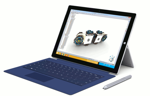
Solid Edge and mobility: Taking your CAD and data mobile
The CAD industry is in a state of flux or transition.
If you’ve been reading your DEVELOP3D issues over the last year or so, you’ll have noticed that there’s a common theme amongst many of the big-name, headline-grabbing systems.
That theme, “the move to the cloud” (a term often employed by marketing types pointing upwards, for some reason), certainly gets column inches. But while the technology world is heading that way, the hard reality is that what users really want are tools and data that are more mobile.
Mobility is a concept that’s often misunderstood. It should be about giving users access not only to the tools they need to get a job done, but also to the data that goes alongside it.
After all, to borrow a carpentry analogy, what’s the point in making a lightweight, ultra-efficient chop saw, if you’ve got no wood to put in it?
Interestingly, the Solid Edge team seems to have realised this and is taking a more measured, tactical approach to making the user community more mobile — and it’s doing so on several fronts.
The first news is that with ST8, when run on Microsoft’s Surface Pro platform, Solid Edge will provide you with a set of interaction methods that are well-suited to the touch-based nature of tablet devices. It won’t be a case of trying to tap a tiny icon to simply pan/zoom or rotate a model.
Instead, you’ll use the familiar two-fingered approach: pinch to zoom, for example.
Of course, because these mobile devices are pretty much a Microsoft Windows box built to a smaller form factor and running the same OS, you don’t need a separate app; you don’t need a constantly available internet connection; and you can plug in your usual devices to supplement your finger and stylus, should you need to do so.
The other news is that Siemens PLM is also looking into ways to provide access to Solid Edge through the browser. Rather than developing a new system or reinventing its own products, the company has begun experimenting with Frame’s virtualisation service.
Essentially, this allows you to log into a portal and run Solid Edge remotely, from wherever you are. No, your data isn’t there immediately, but Frame’s service links into Dropbox and other services to make life easier.
This is currently being rolled out as a new way to trial Solid Edge (there’s a 45-day trial available) and, while the company has no formal plans to make this a general service for users, it’s a good indication of how things may progress in the next year or two.
| Product | Solid Edge ST8 |
|---|---|
| Company name | Siemens PLM |
| Price | starts at £120 for monthly subscription & £2,830 for perpetual for Design & Drafting |




Pingback: Siemens Solid Edge ST8 Gets Good Reviews
Pingback: Siemens PLM CONX ties together users, systems and products | Schnitger Corporation