Representing Autodesk’s first foray into the world of direct geometry editing, Inventor Fusion is arguably one of the most eagerly awaited technology launches this year. First shown at Autodesk University in Dec 2008 where we got the scoop on DEVELOP3D.com, the technology is now available for free download from the Autodesk Labs web-site.
Out of all the CAD vendors, Autodesk has one of the most impressive Labs sites and many core parts of Inventor began as Technology Previews, just as Fusion has now. It is likely to remain in Autodesk Labs for some time as each successive public release is put out for all to see, play with and give feedback to help drive its development – so let’s take a quick look at what all the fuss is about.
LESS IS MORE
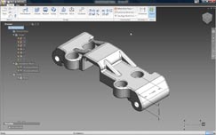
The Inventor Fusion user interface is minimal to say the least and because it has a small set of commands view manipulation is pretty much standard as in Inventor 2010, with keyboard shortcuts for pan/zoom/rotate as well as the ever-present View Cube and Navigation bar to give you quick access to view settings.

Unlike Inventor 2010, Inventor Fusion doesn’t rely on history. Features are still very much an intrinsic part of the application, but it doesn’t carry with it the headache of history recalculation when features are edited
The familiar browser is integrated into the user interface, rather than as a separate panel and gives access to named views, origins, work geometry, annotation planes and a feature list – but no history and this is key, as Fusion is a history-free modelling technology.
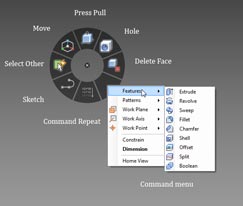
The user experience is highly dynamic with less reliance on toolbars and menus. This is a heads up interface to the extreme. Much of Fusion is driven from marking menus, something that was introduced into the Alias products many years ago and adopted by many modelling packages as a replacement for the context sensitive right hand mouse button menu. Fusion combines the two. Hit the Right Mouse Button (RMB) and a marking menu pops up along with a more traditional menu. This provides access to all of the commands you’ll need – the most important found on the marking menu while the traditional menu gives you a fuller, context sensitive selection.
The sketching workflow in Fusion is very slick. Informal dimensions are placed on the fly, and users can snap and infer relationships while hitting values locks them down (typically for length and angle, using tab to toggle between the two). One thing to note is that Fusion defaults to inches. To switch it to mm, hit the scale key at the bottom right of the screen.
As with most direct modelling systems, there are only a handful of major operations. Press/Pull and Move are the predominant ones. Press/Pull is used to create extrusions, either to add or cut material. Hit the command, select the profile and the display brings up a preview and a small arrow. Geometry can be dragged to the desired depth or values keyed in. With the small glyph near the feature, you can define direction around the plane and a small ball can be used to create the required draft angle when dragged. If you use the Press/Pull command with edges, then you’ll switch to creating fillets.

The Marking Menus provide access to the most commonly used commands around the cursor and a secondary, more comprehensive list of commands are found in a more traditional menu
While the Press/Pull command is used in most instances, the Move command lets you work with existing geometry, grabbing the geometry, for example and using a triad to move or rotate sets of faces. The axis can be locked to specific planes, axes and angles, and using the F6 key, you can also shift it to other reference geometry (such as an edge to get a planar move reference).
Alongside the Press/Pull command, there are familiar commands for sweeps, revolves, fillets, chamfers and shell. There’s a Delete Face operation, but it’s worth noting that the system will only allow you to delete a face if the removal of that face results in a watertight model, once the boundaries have been filled in. There are also patterning tools (radial and linear), mirror of features and part splitting.
Assembly modelling
Alongside the part modelling and editing tools, Fusion also allows you to create assemblies using some basic mating tools. As the system is ‘multi-body in a single part’ capable, you can work with both explicit separate parts or use the same alignment and mating tools to build up an assembly using multiple bodies. Found when clicking the Constrain icon in the Home panel, the basic commands are Align, Centre, Angle and Tangent, all with offsets where appropriate. One thing to note is the order in which you select your mating geometry. As Fusion doesn’t have a fix or Anchor command to lock the first part down, you need to remember that your first selection is automatically locked and the second selection moves to it.
Working with Imported data
Inventor Fusion will read native Inventor data directly but will only import solid data and doesn’t yet support assembly features (such as weldments). In terms of third party data, Fusion supports the importing of SAT files (between version 4.0 and 7.0) and STEP files (supporting the AP214 and AP203E formats). For export, it’ll save out to Inventor format but the other formats are limited to SAT (7.0 only) and STEP using the AP203 standard.
While Inventor Fusion is a non-history-based application it still takes advantage of feature-based working methods. But what about imported data that typically doesn’t have this feature data? To add some intelligence, Inventor Fusion has basic feature recognition tools built into it. Once you have your geometry imported, run the Recognise Features from the Home panel. This interrogates the part and will find any hole, fillet or pattern features and store them in browser. It should be noted that this does not replicate the native features but rebuilds those features that Fusion can work with. The same is true of importing Inventor parts, you won’t get a replication of the native feature tree.
When it comes to making changes to parts, I’ve found it’s best to dive in and work with the data directly, using a combination of the Press/Pull and Move command to edit the geometry, shift it and work with it. When working with direct modelling tools such as this, it is important to realise that all systems have quite specific limitations in terms of topology. While you can move, push and pull faces seemingly at will, the model must remain watertight and closed and the geometry/topology must solve. When you see faces disappearing, this is usually in the area of fillets, where the underlying modelling engine can handle the removal of those faces and patch the surfaces back. Make too drastic changes to complex geometry and you’ll run into trouble. The good news is that Fusion gives good feedback about what the system can do and will clearly flag up problems.

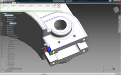
Using the Move Triad and the F5 key allows you to grab geometry, align the triad to the required direction and pull it into position
Summary
Looking at this initial Tech Preview, it’s clear Inventor Fusion is an exciting technology, but there are still many things it can’t do, particularly when compared to other direct modelling systems. One omission is the round trip functionality that was shown at the official announcement earlier this year, where feature data can be maintained between traditional Inventor and Fusion. However, Autodesk is very transparent about the current limitations and a list of things it can’t do is installed with the software, so if you have problems, check that first.
To be frank, I’m in two minds about what to write in the way of a conclusion. This is very early stage software, nowhere near production ready. The technology is going to have the rough spots knocked off before it gets anywhere near integration into core Inventor – which is the eventual goal, rather than a standalone application. So let’s strip it back to basics and look at what Fusion represents.
The most immediate things are the direct modelling tools that allow you to work with geometry in an effective manner, regardless of source. They follow the conventions of other direct modelling systems and it’s clear there’s potential here. While direct modelling is never going to replace history-based modelling, it’s well suited to pure, hardcore modelling operations where history-based systems fail – whether that’s working with imported, dumb data or making design changes at late stages where model history becomes unwieldy. It also provides an interesting way for the non-expert CAD user (but I’d stress the experienced engineer or designer) to get ideas down, play with geometry and to think in true three dimensions – but without the knowledge overhead associated with history-based techniques. These have been the sweet spots for direct modelling for the last two decades and I suspect might always remain so.
What’s changed is that there are now larger vendors jumping into the space that’s formerly been occupied by the likes of CoCreate and IronCAD. If you have bigger players making a lot of noise, there’s a perception that something new has been discovered. The fact is direct modelling isn’t a new concept. What’s changed is market awareness, increased development resources and more powerful hardware to enable those direct edits to be made with less chunking of a processor set.
Alongside the direct modelling, there’s something else afoot with Inventor Fusion and that’s an intriguing experiment or testing of waters with regards to the user interface. Looking at Fusion and separating the modelling technology from the user experience, it’s clear that Autodesk is testing out how users react to the new marking menu system, a much more interactive heads up way of working than is currently implemented in Inventor 2010. What I find intriguing is that Autodesk is doing this by releasing code into the public realm and letting users (whether they’re customers or not) play with it and see what it can do. That can’t do anything other than assist with making a better product.
The two in combination certainly make for an interesting development. Some new technology that’s at a very formative stage, still awaiting some of the core components, and which is going to extend well beyond this calendar year with updates. Let’s see where it goes.
{encode=”al@x3dmedia.com” title=”al@x3dmedia.com”}
| Product | Inventor Fusion Technology Preview |
|---|---|
| Company name | Autodesk |
| Price | Free for download |


