This month we turn our thoughts to the idea of Principal Stresses – these are simply the direct stresses, at arbitrary angles, such that NO SHEAR STRESSES act with them. In a very simple structure (say a bar aligned with the global X-axis) the global direct stresses may exist without shear stress so these are Principal values already. In general however the Principal Stresses will occur at arbitrary angles (to the global) and we can compare Cartesian Stresses and Principal Stresses in the following manner:
Cartesian Stress: Tensor with three direct and three shear stresses in GIVEN directions
Principal Stress: Vector of three Principal Stresses acting in ARBITRARY directions
The Principal Stresses are calculated from the cubic formula (eek sorry):
p3 – I1 p2 + I2 p – I3 = 0
Where the above “I” values are the stress invariants (quantities that don’t change as the stress field is rotated) and I1 is given by the sum of the direct stresses (a nice check for later on). The above formula will (always!) yield three Principal Stress values and we usually denote the most tensile value as “P1”, the most-compressive as “P3” and the one in-between as “P2”. Once we have the three Principal Stress values we can deduce the directions they exhibit (usually as unit vectors in the global system). You should envisage the Principal Stresses as three direct stresses mutually perpendicular to each other (with no shear stress defined on these planes). Let’s look at an example:
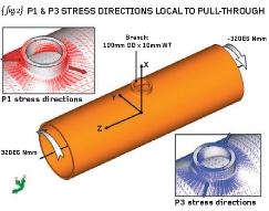
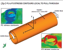
{ figs.1 and 2} show a tubular member (or “header” – imensions 300mm OD x 10mm WT) with a minor member (or “branch” – dimensions 100mm OD x 10mm WT) “pulled-through” from the side wall of the
main member. We will need to assume that the tube is annealed such that any manufacturing stresses are removed before we apply some external load.
The tubular member is then subjected to a torque of 320E6 Nmm at one end (Z+) and an opposite moment/torque at the other end. The tubular member is shown as a “free-body diagram” because it is under force and moment equilibrium (we covered this in an earlier article). The applied load is shown on { figs.1 and 2}.
The loading induces a state of pure shear in the member (there is NO hoop stress, axial tension, bending stress and so forth and so on). Check yourself but a simple hand calculation (shear stress = Tr/J) shows that the shear stress on the outer diameter of the main tubular will be 250MPa (away from the penetration).

Fig.2
Trust me but theory dictates that the resulting Principal Stresses will be: P1 = +250MPa; P2 = 0 MPa; and P3 = –250MPa in areas away from the influence of the branch. The subsequent principal directions occur at +45 and –45-degrees to the main axis of the tubular. In other words the applied torque (twist) has resulted in pure tension at 45-degrees one way and pure compression at 45-degrees the other way. These two Principal Stresses are helical in nature and parallel to the outside surface of the tube. The third Principal stress is normal to the surface and, for equilibrium with the applied pressure (there isn’t any!), must be zero. A state of (two-dimensional) plane-stress exists on the OD of the tube (as one of the Principal values is zero).
An approximate Finite Element Analysis model has been constructed in order to prove the theory as stated above. (We will return to the accuracy of such an analysis in future articles). P1 and P3 stress contours local to the pulled-through brace are shown on { fig.1} while the associated principal directions are shown in { fig.2}. It is apparent that the principal directions predicted by the FEA are in the plus-45 and minus-45 directions and the resulting tension/compression is consistent with the direction of the applied torque.

Fig.3
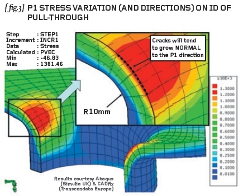
{ fig.3} shows a detail view of the peak P1 stress predicted on the internal blend between the main header and the minor brace. The P1 direction is seen to have changed to the circumferential direction around the brace. Note that any cracking/tearing starting from this peak location will tend to be in a direction NORMAL to the P1 direction – a useful plus-point for the use of Principal Stresses. The predicted Cartesian Stresses at the P1 peak are as follows:
Sxx = 311.3; Syy = 619.0; Szz = 930.5; Sxy = 271.2;
Syz = 565.1; Szx = –24.2MPa
And the resulting Principal Stresses are P1 = 1,381.5; P2 = 473.8 and P3 = 5.6MPa. Note that the P3 stress is normal to the surface in this case (near zero).
Finally, a little bit of homework: are you happy that the first stress invariant does not change?
R P Johnson BSc MSc NRA MIMechE CEng – technical director, DAMT Limited

Part five of an engineering master class, this month: Principal Stresses


