Creo 5 – Creo is almost one-third of a century old, but recent releases of PTC’s flagship design and engineering product have seen new life breathed into the venerable system. We explore what the latest release brings to the game
With its roots in Pro/Engineer and the founding of the parametric, history-based modelling industry, Creo has come a long way since the late 1980s. Over the intervening period, the system has grown in coverage and now encompasses design, engineering, simulation, manufacturing and much more.
![]()
Creo 5 retains its familiar user interface, but delivers new widgets that allow you to focus better on the task at hand
It has subsumed other technology along the way (CoCreate and its direct modelling capabilities spring to mind), and today, it’s a behemoth of a system.
The company behind it, meanwhile, has similarly grown and spread its wings. So what’s coming up in Creo 5?
Let’s start by looking at the updates and enhancements that will be broadly applicable for the majority of users, rather than those who fit into more ‘niche’ categories.
In terms of user interface, Creo has been pretty consistent over the last few releases, with the majority of changes focused on adding in more modern touches that users have come to expect from their software.
Creo is incrementally being modernised, but in a manner that’s manageable for its long-standing and highly experienced user community: it now comes with a full-screen mode backed up by context-aware mini toolbars, box selection and geometry regions in sketching (as opposed to fully trimmed sketch geometry).
Mini toolbars are also available across a much wider spread of the system’s modules and in both 2D and 3D environments.
Additional updates to core modelling tools include changes in the way that the system handles adding drafts to parts that also feature rounds. Rather than trying to wrangle the whole thing, the new operation works in the background, removing rounds.
It then applies the draft to the required faces and reapplies the rounds. On this point, it’s also worth noting how Creo has some very interesting options when adding draft to components; specifically, building in drafted faces around a centre or split line.
Whereas other systems require you to split faces, Creo’s draft operation has options to use a mid-plane and handles all of those problematic facesplitting operations for you.
The last general update I want to cover is the introduction of volume-based helical sweeps. While this works just like a standard sweep feature, the difference here is that rather than sweeping a simple planar profile around the path, in this instance you’re using a geometric lump. It’s a small, rather subtle difference between the two, but the resulting feature is very different and is required for many different purposes, since volume sweeps are particularly useful for cams for mechanisms and some more complex thread forms (think drill bits).
Freestyle, style & ISDX
Now let’s dive into an area in which Creo has been strong for many years – the use of industrial design-focused tools for complex shape development.
When we say ‘complex shape’, we’re talking about traditional surface modelling, where curvature continuity is essential, form control is paramount and in more recent years, the use of subdivision surface modelling technology has emerged. Creo’s offerings in this area are split across two areas.
The Style module (part of the Interactive Surface Design Extension or ISDX toolset) provides traditional surface modelling tools you’ll need, while the Freestyle module brings subdivision modelling tools to the game.
Updates to the Style model for this release are minimal; after all, this is a set of tools that has been developed for 20 years or so, and has already reached a certain level of maturity. That said, there’s always room for improvement or adding a little more intelligence.
For example, when you build a G3 (curvature continuity) relationship between two faces, the system automatically handles upgrading the curves that also define the connecting edges of those faces to the same level of continuity. This is something that would have taken a fair bit of manual work to accomplish previously.
Now, when creating new curves, you have the ability to specify a symmetry option, in order to build lighter weight curves spanning a mirror plane. With this comes the option for mirroring curves directly inside Style.
On the Sub-D modelling front, the biggest update to Freestyle is the ability to switch to a box mode for editing heavier, more geometrically rich models. This will be familiar to those users who have used other Sub-D tools. It shades the control mesh, giving you a coarse, faceted representation, but what it gives up in resolution, is gives back in interactivity, with much snappier responses to edits and providing greater clarity over the topology of the control mesh.

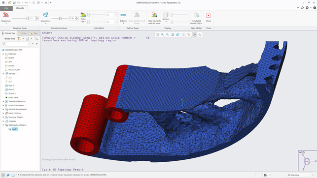
Creo 5 introduces a topology optimisation solver that gives you a wide range of boundary constraints and performance requirements to apply to a starting form, resulting in the familiar mesh

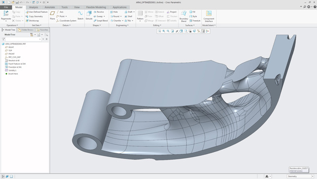
The system will skin the model using sub-D, Freestyle geometry, in order to give you a more readily usable model
Creo 5 – additive manufacturing
Let’s talk about additive manufacturing for a moment. I think we’ve all seen how 3D CAD vendors have jumped all over the additive manufacturing industry, with a view to pushing new functionality in their software tools.
In fact, I don’t think I’ve seen a major software system released in the last few months that hasn’t referenced topology optimisation in some form or another.
As you might expect, Creo 5 is no different in this regard. Where it differs, however, is how the process fits into both the existing design and engineering workflow and Creo’s data structure. While Creo 4 brought us the ability to define lattice structures in our parts, Creo 5 starts to introduce both a new topology optimisation engine and a way to do something useful with the resulting data.
First things first, the optimisation process: Creo’s tools are built on the VR&D solver, Genesis. You then step through the familiar process of defining your boundary conditions, keep-in areas, keep-outs and so on, as well as optimisation targets (for minimising mass or displacement or maximising stiffness) and load case (or multiple cases, if you have the higher end module).
These are all then used to generate a mesh-based form that solves those criteria.
At this point, many topology optimisation tools top out, leaving users with no choice but to use this mesh as the ‘inspiration’ for a reworked solid and surface model.
What Creo does differently here is to provide an operation called Geometry Reconstruction. This uses a patch network of Freestyle subdivision surfaces, which is laid over the mesh and snapped into place. There’s no manual remodeling or skinning the model.
A simple click and it’s done. Depending on your resulting model, the freestyle model entity will be complex, but it does means that you can integrate it into subsequent operations, whether that’s adding more engineering features, machining stock for post-processing or something else.
It’s worth noting that this module is available in two flavours. First, the entry-level flavour (snappily entitled ‘Creo Topology Optimization Extension’) allows you to define both structural and modal analysis types as part of the optimisation process with symmetric, cyclic symmetric and extrusion and filling as manufacturing or form constraints. It also limits the number of load cases used to inform the optimisation process to three.
Second, the Extension Plus variant opens up the number of load cases you can define, allowing you to include thermal analysis as an optimisation consideration and giving you a much wider range of constraints such as stamping.
Another additive manufacturing-related update for this release is the introduction of technology from Materialise’s range of Build Processors, which specifically target metal-building machines. Essentially, this means that you can design, engineer and test your metal parts in Creo, then also within the system. You can start to explore how to manufacture a part on a machine from the likes of Arcam, EOS, Renishaw, SLM, HP and Concept Laser and lay out your build chambers, generate your supports, experiment with orientation and so on.
Integrated CFD
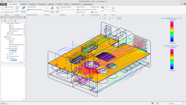
Another brand-new area of functionality is the introduction of Computational Fluid Dynamics (CFD) tools directly inside Creo.
While there’s been a series of add-on tools for CFD work for Creo for a while, this is the first time that PTC has released something official and listed in its price book. The technology it has used is the Simerics’ solver, which while not being one of the big names in CFD, still has a very loyal following.
In terms of the Creo implementation, the workflow is pretty standard. You begin by defining the type of study you want to perform, whether it’s of an internal environment (for example, pumps or cooling inside an electronics enclosure) or an external environment (aerodynamics, for example). You then define the types of physics you want to use.
From there, you start to define your CFD domain from your CAD model. If you’re running an external study, this will be pretty easy as you’ll have your model ready to go. If you’re running an internal flow study, then you need to generate your fluid volume. Here, having your CAD model inside a powerful modelling system comes in handy, as creating your fluid volume is pretty much a single button push, once you have your inlets and outlets capped off.
Then it’s a case of defining boundary conditions, the inlet, outlet and fluid details, and running your study. You’ll find that the whole process is neatly integrated into the Creo interface, with all of your study requirements managed through the panel to the left-hand side of the UI. Your interaction with results, meanwhile, is just as you would expect.
Again, as with the topology optimisation module/extension, the CFD tools in Creo (called Creo Flow Analysis) are modular in nature. The base-level package (at around the $2,000 mark) gives you the basics for flow simulation, heat transfer and turbulence. The middle package adds in particle tracing, radiation, fluid mixing and moving frame simulation, among other features, and costs around $5,000.
If you want to dive into the world of cavitation, multiphase CFD and more complex dynamics, then you’ll need to get the Premium package and pay a much higher licence fee.
Creo 5 -model-based definition
Like other technology vendors focused on the large-enterprise end of the 3D design spectrum, Creo has been gaining 3D GD&T (or PMI) tools for some time now.
Creo 4, for example, introduced a new module that guides the user through the standards-based application of annotations to a 3D model. Built in partnership with Sigemtrix, a specialist in this field, the module handles the process neatly and efficiently, allowing to you quickly generate data that conforms to your chosen standard and checking it is fully constrained.
Creo 5 extends this work, to allow you to add semantic queries into your model using the GD&T you’ve already defined. So when design changes occur, or you are driving your part in an automated fashion, then it’ll help rip through any GD&T that becomes disassociated with the originating or reference data.
This release also sees the start of work to automate the creation of drawing views from 3D PMI-enabled data. This first instance allows you to quickly print or PDF fixed, formalised ‘state views’. While you can’t currently arrange these on a set of drawing sheets, you can see where things are headed.
Creo integrated CAM
It has been a while since PTC talked about Creo-integrated CAM code. As long-term Pro/Engineer-era users will know, PTC has always had CAM tools available and, over ten years ago, these were boosted with the company’s acquisition of NC Graphics. But with the release of Creo 5, this topic has reemerged as a talking point.
In short, there’s a new set of CAM tools available in this release, based on the ModuleWorks CAM engine, and addressing subtractive manufacturing machinery from common or garden 3-axis high-speed machining operations to 3+2 operations. (As yet, there’s no word on simultaneous 5-axis as yet).

Creo’s new CFD module allows you to conduct fluid flow and heat transfer type simulations
Creo 5 – augmented reality & IOT
The final subject we’re going to cover is PTC’s work on Augmented Reality (AR) and the Internet of Things (IoT).
This has advanced considerably since Creo 4; in that release, for example, the company introduced a set of tools that allowed the user to generate an AR dataset that might be shared with anyone, directly from the application.
In Creo 4, this converted your Creo model, allowed you to add in a ‘ThingMark’ that enabled the viewing app to ID the correct dataset (they are cloud-hosted), and gave it scale. While this was a subset of PTC’s Vuforia tools, it proved interesting and easy to use – particularly key for getting folks to try AR as a means for design review.
For Creo 5, this work has continued. In the first instance, the capability has changed so you don’t need the Thingmark for scale.
Instead, the apps will use spatial tracking and an awareness of surrounding elements to work out how to display your model at the correct, defined scale. This alone is pretty damn impressive.
In addition, you also have a greater set of controls over access to the data you create, such as password access control that helps to to enforce who can view your AR data.
On the IoT front, Creo 4 saw a bunch of tools introduced that made it possible to link Creo models to IoT data stored in PTC’s Thingworx platform. Creo’s Product Insight Module, for example, allows users to connect to data from a physical product, whether that’s a live one-to-one link or one that uses aggregated data.
With further development for Creo 5, you can now build in sensors within your digital model that will match up with sensors in the physical realm and, importantly, use that integration within the simulation environment. So what does that mean?
In short, it means that you can not only move your digital model using data from the real world, but also use physical sensors to drive simulation studies. The potential for this is huge, but there are also a few additional tools that we’ve heard about that will make this even more powerful, in the coming months, so stay tuned around June.
In conclusion
A couple of years ago, you might have been forgiven for thinking that the leadership of PTC had all but given up on the core 3D CAD portion of its business. The IoT and service management world was seemingly where its real focus lay.
But it transpires that what the company has actually managed to do is to broaden its focus to the brave new world of the IoT, but in a manner that means that 3D design and the data it creates take centre-stage.
That strategy seems, in turn, to have had a dramatic knock-on effect on the development resources committed to Creo, as the last few releases of the package have been impressive.
Creo 5 doesn’t disappoint, either. The company is clearly serious about additive manufacturing and, considering its position in automotive (in particular, powertrain) and aerospace (particularly the defence end of the spectrum), as well as some of the other transportation industries, it’s no surprise.
What’s interesting is how PTC is addressing the whole workflow, from optimisation of form according to function, to allowing you to plan manufacturing inside your design tool, and then onto enabling the machining of optimised forms and post-processing work.
This is an aspect that many other vendors have missed entirely. Then there’s the work PTC is doing on bringing digital design and engineering systems together with the physical world, allowing user to not only drive assembly dynamics, but also conduct simulation work using real-world capture data. Again, this is something that few other vendors are doing right now.
But consider the impact if you successfully link those two areas up. Imagine an assembly, for example, that is directly linked to variants already out there in the field, an assembly that can use real-world data to drive optimisation routines on key components, adjust those that are underperforming (or indeed, are over-engineered), simulate a new, better form and prepare it for manufacturing. When you think about it, that’s quite something isn’t it?
| Product | Creo 5 |
|---|---|
| Company name | PTC |
| Price | on application |


