
High-frequency antennas are traditionally built by fabricating and assembling dozens to a hundred or more individual components plus hardware to provide the required radio-frequency (RF) performance and structural integrity.
The RF energy propagates from component to component through interfaces, seams and discontinuities, so the RF path length must be increased to compensate for these obstructions.
Each component needs mounting surfaces and hardware, which add more unnecessary weight and space. In addition, part material thickness must be suitable to meet design- for-manufacturing constraints, and extra space is needed throughout for assembly clearances.
At Optisys, we believe we have found a better way to handle this complex process. Using engineering simulation, cloud-based big compute and 3D printing, we achieve orders-of-magnitude reductions in antenna size and weight, while reducing development times.
In particular, by leveraging electromagnetic and structural simulation tools from Ansys, running on a big compute platform from Rescale, this start-up’s engineers can take full advantage of the design freedom offered by 3D printing to meet RF performance requirements for integrated array antennas.
Advances in metal 3D printing now make it possible to fabricate antennas and RF components at the scale required for wavelengths in the millimeter range.
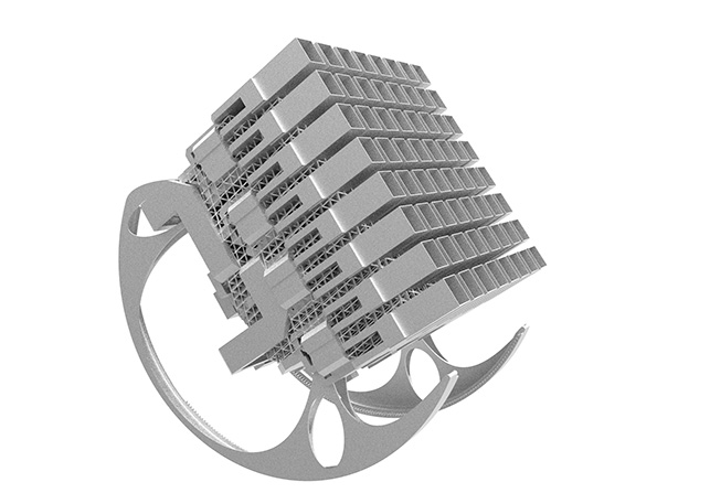
An entire antenna can be printed in one build as a single component.
The elimination of interfaces, seams and discontinuities makes it possible to substantially reduce the length of the RF path and the absence of mounting surfaces and hardware provides further size and weight reductions.
Further reductions can be achieved by decreasing material wall thicknesses. And because assembly clearances are not required, engineers can make still further size reductions by packing features tightly into the entire 3D volume.
Optisys engineers used Ansys simulation software to deliver order- of-magnitude reductions in size, weight and development time for the new 64-element X-band SATCOM integrated array antenna (XSITA).
The amount of simulation required to perform such a feat is incredibly compute-intensive, and Optisys does the bulk of simulation on Rescale’s cloud platform for high-performance computing (HPC), minimising its on-premise IT footprint.
Optisys – Revolutionising Antenna Design
3D printing is revolutionising high frequency antenna design by realising levels of integration and performance far above conventional fabricated antennas. To gain the full potential benefits of 3D printing and other new manufacturing processes requires engineers to redesign antennas from scratch.
This is a long and laborious task using traditional RF design methods, which involve hand-calculating an initial design, building a prototype, testing the prototype and then tuning it manually.
These steps are repeated over and over until the design meets all specifications, a process that can take a year or more.
To evaluate a broader range of alternative designs and iterate to an optimised design before building a prototype, Optisys uses simulation.
By joining the Ansys Startup Program, Optisys gained access to Ansys’ HFSS electromagnetic simulation software and its mechanical finite element analysis software to evaluate the RF and structural performance of its design.
Engineers create simulation models locally and upload them to the Rescale cloud platform where they can run Ansys software natively and access powerful high-performance computing resources without having to maintain a computing infrastructure on-premise.
Rescale complies with International Traffic in Arms Regulations (ITAR), so Optisys is able to use the platform even for antennas used in defense and homeland security applications.
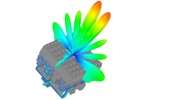
Optimising the RF design, Optisys engineers parameterised their initial concept design and used HFSS to calculate the S-parameters of each section of the antenna. They used the Ansys Optimetrics electromagnetic optimiser to evaluate multiple design variables at a time based on the S-parameter results, primarily considering how much of the RF input was transmitted, versus how much of it was reflected back.
The optimiser stepped through the design space by following gradients toward an optimal design that minimised insertion losses and reflected energy. Engineers frequently generated e-field and surface current plots of the waveguide cavities for the designs generated by the optimiser, in order to visualise performance and determine which areas most needed improvement.
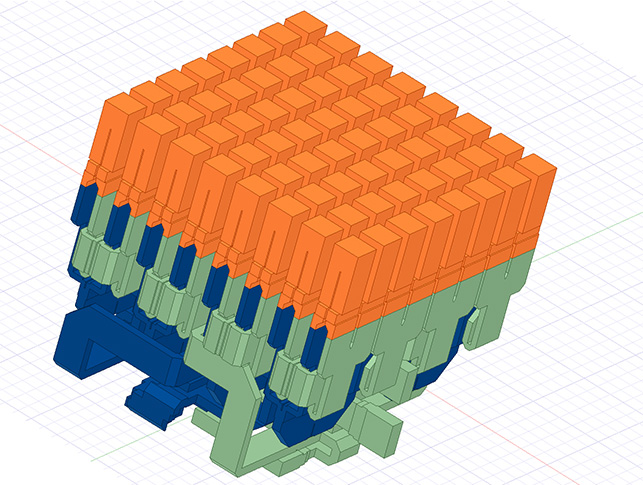
The XSITA radiating elements consist of 64 square waveguide elements with chokes formed from the structural supports.
Both left-hand circular polarisation (LHCP) and right-hand circular polarisation (RHCP) are generated, based on a classical 2-port septum design that transforms a single mode input to a circularly polarised output.
The LHCP and RHCP networks were designed so that each quadrant of the full radiating element array is broken into four- element by four-element subsets.
The polariser outputs connect to a 16-to-1 corporate feed network that pulls down each quadrant into combiner networks that feed into monopulse comparators.
The RHCP and LHCP outputs have separate monopulse comparators for tracking on both polarisations, resulting in eight total output ports. The monopulse comparator for each polarisation is nested among the bottom sections of the corporate feed in a compact manner that adds as little extra additional volume as possible.
Due to the high levels of integration, with waveguide spacing approaching 0.020 inch in multiple regions, it is necessary to route the waveguide paths with all components of the model visible, but only simulate a subset of the geometry to improve simulation speed for optimisation.
HFSS makes it possible to include or exclude geometries from the simulation without removing them from the modeller window.
This makes it possible for Optisys engineers to independently design the RHCP and LHCP networks, while winding them around each other to minimise 3D volume and waveguide length.
Designing Structural Support
Engineers used Ansys Mechanical to analyse the lattice support structure to ensure sufficient mechanical strength to allow for reducing the thickness of the RF components to minimise the weight of the antenna.
Engineers also designed a printed elevation axis that includes a rocking arm and gears and connects to an external motor.
The design of the XSITA array showcases the level of integration that can be achieved with 3D printing when engineers leverage Ansys HFSS to optimise complex RF designs and the power of virtually unlimited scaling available on Rescale’s cloud HPC platform.
The success of start-ups like Optisys depends on delivering innovative solutions to the market faster than better-funded organisations.
Combining engineering simulation with the ability of Rescale’s big compute platform to parallelise multiple projects, meanwhile, provided Optisys with massive efficiency gains and the ability to reduce design cycles from months to weeks.
The results speak for themselves. Existing antennas in this space average 50 pounds and contain more than 100 components. By contrast, the Optisys XSITA weighs a mere 8 pounds and consists of a single component.
Being able to innovate in this way enables a start- up like Optisys to compete in this new field of 3D printing, which is expanding exponentially and enabling unprecedented capabilities.
Using simulation, cloud and 3D printing tech to drastically reduce the size of antennas
Default