Long time readers of DEVELOP3D will be familiar with Delcam and its PowerShape system — for those that aren’t, it’s worth a quick recap.
PowerShape’s direct modelling tools build on the system’s existing geometry editing tools to make them more dynamic and interactive
While other applications in the design space get all the headlines and have the huge communities of users, PowerShape has differentiated itself over the last decade as a system that lets you wrangle geometry — all sorts of geometry.
Due to Delcam’s heritage in the manufacturing sector, PowerShape allows you to work with explicit surfaces and more recently with parametric solid geometry (it’s now even got the venerable Parasolid kernel built in). It’ll let you combine these with triangle or polygon data to create highly organic product geometry. Basically, if you can represent something with 3D geometry, PowerShape can handle it.
This, even in an industry over 30 years old, is a rarity. Essentially, it is one of the very few systems that lets the user work with the data they’ve got and the data they need to use.
Alongside this, Delcam has been carrying out some consolidation of its other design related tools into the PowerShape application over the last few releases.
While CopyCAD has been around for some time, bringing together a suite of tools for manipulating, fixing and working with scanned data, the Delcam team took the decision to introduce the same functionality into PowerShape Pro.
This trend continues in the 2013 release and it’s worth exploring further.
Re-engineering
While the last release saw the introduction of some of the ground level tools from CopyCAD, this release sees the toolset become much more fully fledged.
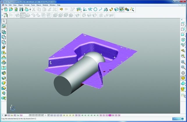
For example, it’s now possible to use a scanning device directly into PowerShape Pro. To support this, greater filtering tools have been introduced that allow the user to remove noise from the scan data.
These are then backed up with manual trimming and tidy up tools to get a nice clean set of points ready for the next stage — triangulation.
The tools in PowerShape Pro enable the user to do an initial triangulation. Then some hole filling and automated smoothing tools are used to further improve the scan.
Another area that’s been reworked is the ability to align the scan data in 3D space. Those experienced with laser scanning to CAD workflow will know that it is, at best, pot luck how scan data is actually held in 3D space.
That’s fine if scanning to 3D print, but if the data is needed to build more explicit CAD geometry, then the user needs to be able to align and fix it in a sensible position. This can be carried out using a variety of selection and reference methods in this release.
Once done, the user can then use all of the geometry modelling tools in PowerShape; solid features, surfaces, even the polygon mesh data, to create the form needed. It’s also worth noting that there’s a nice comparison feature that allows the user to check the eventual shape (or while in progress) against the raw cloud point.
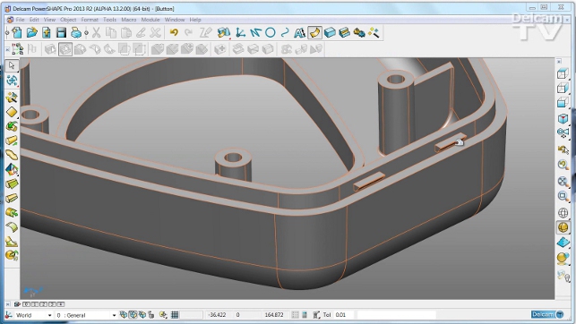
Direct Modelling
Alongside the reverse engineering tools, Delcam has also introduced a lot of direct modelling features over the last few releases.
PowerShape (as is common in many mould and die-focussed tools) has always been able to manipulate geometry, down to the face and surface control point level. What has changed is how these tools are presented to the user and the terminology and accessibility of those.
This brings it in line with the expectations of today’s users as direct modelling has become more widely understood.
A good starting point is the feature recognition tools — something that’s essential to make good use of direct modelling. PowerShape can find the usual suspects such as fillets, chamfers, holes, pockets and bosses.
It’ll then allow the user to manipulate the faces or sets of geometry as required. The system can defer updates until all the edits have been made and then they can be applied all at once. Each edit gives a full preview, making the user aware of what the result will be. If an edit can’t be made, then the Solid Hints tool kicks in and gives guidance about what’s wrong and how it can be fixed.
Electrode solution
Building on the new direct modelling tools, PowerShape Pro also sees a new set of tools introduced for electrode design.
This isn’t the first time Delcam has created a tool for extracting the geometry, building up the electrode and creating the manufacturing information needed.
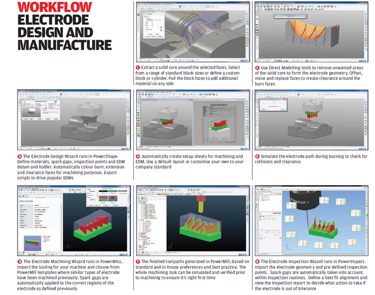
But this is the first time it has been built directly into application. To give a flavour of how it works, the direct modelling tools are used to select and extract the geometry from the cavity or core. This is done using a bounding box or selection of the faces.
An automated wizard is then used to define the electrode stock (all driven by standard forms and catalogs). Spark gaps are then added where needed. The next steps are preparing the manufacturing data, not only in terms of tool-paths for machining the electrode itself, but also inspection points (for use in Delcam’s PowerInspect metrology application).
Tool-paths are generated using PowerMill, then documentation creation for the machinist and EDM operator. Incidentally, all of this information is stored in a single file with the .trode extension, making communication and tracking of work much easier in a dispersed team.
Nesting
The final big update for this release is the introduction of nesting tools.
Readers engaged in working with sheet metal forms will be more than familiar with the process, but for those unaware, it’s the process of optimising material use given a specific sheet size and a part list.
Essentially, PowerShape can nest any forms (either sheet form or 3D part) on a 2D plane. It has quite sophisticated tools to control offset between parts and whether parts can be mirrored or not, plus rotation controls (for those looking to maintain grain orientation).
The tools allow specific parts to be jiggled, while remnants can be saved out and reused.
Conclusion
PowerShape is an impressively well developed set of tools for design — and not specifically in the mould and die arena for which Delcam is perhaps best known.
The depth of geometry creation and modification tools, encompassing not only surface and solid modelling, but point and polygon mesh handling, are first class.
The work done over the last few releases shows that Delcam is not only taking notice of where the current 3D CAD industry is going but also using its mastery of the more difficult tasks that other vendors shy away from. The direct modelling tools are an excellent example of this.
Delcam has always allowed the direct modification of geometry, but the current set of tools formalises things nicely. Where many direct modelling tools break down is working with ‘less than ideal’ geometry, whether due to poor modelling, poor tolerances or just poor geometry.
PowerShape is one of the few systems that provides a full set of tools to dive in and fix, repair or reconstruct the geometry so you can get the job done.
PowerShape (the base package including solid, surface and direct modelling) is £5,000. If you want to add in the reverse engineering and triangle modelling tools with the PowerShape Pro package, it’s just an additional £2,000 (electrode wizard is an extra £2,000).
For anyone working with complex geometry, it’s worthy of investigation and considering that a fully functioning version (with no export capability) is available to try, I’d recommend it to anyone interested in investigating an alternative to the more mainstream packages out there.
| Product | PowerShape 2013 |
|---|---|
| Company name | Delcam |
| Price | From £5,000 |