In the previous review of VISI 18 we took a look at the design oriented tools within Vero’s flagship VISI product discovering a system that has improved and expanded its capability.
Combination finishing routine based on angle ranges
Here we turn our attention to the world of manufacturing – an area in which Vero and VISI earn their collective bread and butter. So, let’s begin with something that’s often overlooked by many CAD/CAM software developers: progressive die design.
VISI Progress
Progressive die design involves a fascinating process in terms of workflow. It essentially starts with a part, typically sheet metal in nature, and works it backwards to arrive at a blank form.
The user then creates the punches and formers at each stage taking the developed blank to final form. The actual tool is then designed around those entities.
When complete, the die is built, the sheet metal is fed in and out pops a typically complex component. This may seem counter intuitive for those not experienced in the industry, but it works beautifully.
The first part of the die design process is perhaps the most complex. While the folded form of a component can typically be defined in a single operation for each fold, unfolding that same form for each die stage is often much more involved.
Firstly, some bends need to be applied in multiple stages, either to purely achieve an extreme change in angle or to allow the die to create other features.
Additional complexity arises as the progressive die design needs to account for not only the bending and punching of materials, but also for the distortion and stretching of the sheet metal as it progresses through the process.
In essence, it’s not just a case of flattening out a sheet metal model of a part and using it. The flanges also have to be unfolded.
In VISI Progress 17 flange unfolding was substantially improved. This release sees that work mature with disparate commands and options consolidated into a handful of operations.
These are context and selection sensitive so that the geometry the user selects will predefine the method used to fold specific geometry. There’s also greater feedback and reporting on the more complex operations, such as using a binder surface to unfold complex faces.
This allows the user to predefine a sheet form onto which flanges will be developed. The system then calculates the deformation in order to provide an accurate geometric form. For this latest release the forming process is now animated and coloured feedback shows where thickening or thinning of the sheet metal will occur.
There are also tools to show how edges are shifting between each stage. For instance, constraints can be added to hold specific edges in order to maintain particular features.
Finally, after completing the blank development, it is possible to generate a HTML report that provides all the relevant information for the production of the part. This includes weight, theoretical thickness,
area, perimeter, plus additional details for all internal forms. Information like this is vital when preparing a quote.
Next up for VISI Progress 18 is greater support for the smaller details such as Ribs and Bosses (or, to use the more common parlance, Bird Beaks), which add strength to parts.
As these have a dedicated feature, the user defines the geometry on which to base them (essentially a line), and then picks the geometry to which they’re applied.
Also key is a new ability to integrate assembled components into the parts at individual stages. This ensures that the stages defined in production will allow these intermediary steps to be performed and that the folding or production process doesn’t foul with the die during fabrication.
A typical die stack consists of a number of plates, each with different apertures for punches and for slug removal. VISI 18 sees the introduction of some automated features to aid the assembly and manufacture of the common features.
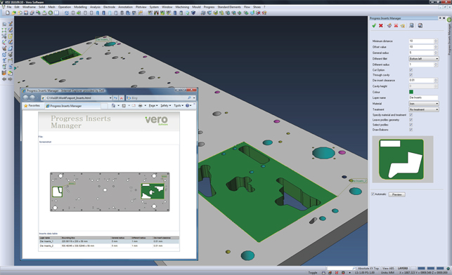
First off, VISI Progress is able to apply relief holes to vertical edges of internal pockets and automatically assign feature attributes that can be used to generate drilling tool-paths. Second is the ability to create automatic die housing inserts, which include minimum distance checking and key corner radius adjustments to avoid incorrect assembly.

These are replaceable components that would typically experience the most wear and tear during the die’s life cycle and are usually made of hardened steel. The system will ensure that multiple inserts in a single plate don’t come too close together as this can cause weakness in the assembly.
It will then spit out a report with images and dimensions for production as well as positioning details if required. The last update is a new Blanking Batch file into which files can be added, development parameters set up, and then the system can chunk through the list, generating the blanks where needed.
VISI PEPS-Wire
Vero acquired UK-based Camtek Limited some time ago and its tools, including the PEPs suite of specialist CAM technologies, are now beginning to merge into the flagship VISI product.
PEPS’s mastery always lay in the field of Wire Electrode Discharge Machining (EDM). This is linked heavily to the more mainstream world of 2.5-axis machining, but has a very different requirement in terms of capability and control as well as integration with a range of specialist machines.
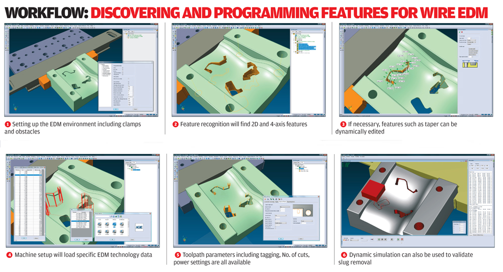
It starts with feature recognition that finds not only parallel-sided pockets but also those with land and taper, variable land and more complex 4-axis tapers (which are most commonly used for extrusion dies and large scale mouldings).
Next, the user works through the features, adding in the necessary start holes and approach points. The system then presents a machining operation best suited to the geometry at hand.
For example, if it’s a parallel or tapered aperture, it’ll present 2-axis operations whereas a 4-axis operation will be offered for more complex ruled surface features. Of course, for more simple wire-EDM type jobs, a 3D model isn’t always necessary or available and in these cases operations can often be driven from 2D geometry just as efficiently.
In practice, the user switches to the Wire environment, selects the features to work with, and uses the appropriate technology for a specific machine tool (VISI PEPS-Wire has a wealth of predefined technology for a lot of different machines) and filtering operations to define the toolpaths required.
These can be either automatically created, or in more complex scenarios, perhaps due to machine head movement or intricate geometry, taper, approach and exit angles can be manually edited. Tagging is also critical for Wire-EDM processes, as users may want to retain the slug for removal at the end of all the machining operations or have the slugs removed as early as possible.
Finally, as the system is integrated into VISI’s existing machining-related products, advantage can be taken of the system’s full suite of machine and part-based simulation and verification tools. This ensures that the part runs well, with additional tools used to help remove the slugs resultant from tapered or 4-axis pockets.
VISI Machining
VISI is best known for CAM and Vero has been in the game for quite some time. In fact, many of the other CAM vendors license the same code on which to build their applications.
At present the toolset is incredibly well developed and runs a wide range of machining operations and types. From basic 2.5-axis production machining jobs into the more complex world of surface machining for tool and die applications.
In terms of updates for this release, a major focus is on building greater support for mesh geometry. We covered this in general in the previous review, but with specific reference to machining Vero has now added tools that allow the user to manipulate the mesh that underlies all CAM operations (N.B. the majority of machining systems use a tessellated mesh rather than the surfaces on which to build tool-paths).
In practice this allows users to take that mesh and quickly create an offset. An example is adding machining or grinding stock to a casting, something that might be very difficult to achieve using surface geometry.
Another addition is the ability to edit mesh parameters for local areas on the model. This allows the user to tighten up the machining tolerances in critical areas without penalising the calculation time by applying smaller tolerances across the entire model.
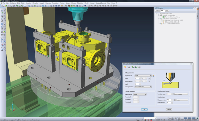
Interactive drilling
The new release has also seen work done on interactive drilling cycles. This provides complete flexibility regardless of model topology and allows users to find holes and select them individually to create a toolpath.
In essence, overriding the automated tools, the user can make changes that might not be inferred from the geometry recognition alone. For example, rather than re-modelling a couple of holes as a
result of a design change, the user can simply edit the diameter of both holes interactively from the tool-path execution.

This type of control is then extended to the Interactive Milling tools, which allow users to manually create and edit simple 2D machining tasks. Essentially, this means defining the cutter, sketching out the tool-path using simple mouse clicks, and creating offsets to the depth and number of steps required.
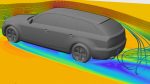
The last two major updates for machining are as follows. Firstly, a new feed-rate reduction option allows users to define a maximum/minimum angle and reduce the feed-rate in those ranges. This allows for greater control over cutting speeds as the tool climbs up and down walls.
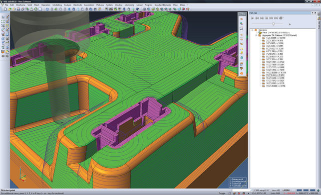
Secondly, there is a brand new tool-path/operation type called Aggregate Machining. This is most useful for highly complex geometry where users can mix and match machining strategies for steep and shallow areas in the same part.
The model is broken down into individual zones based on angle ranges into which a separate toolpath strategy can be applied. In previous releases, this was created as a single tool-path.
However, from VISI 18 onwards, it can be split it into separate operations over which the user has finite control of the toolpath type including raster, spiral, radial, morph, waterline and constant step-over – after all, these are typically the final machining operations and for those wishing to achieve the highest surface quality possible, a high degree of control is needed.
Conclusion
Over the last two issues, we’ve discussed all of the major updates to the VISI product range for the 18th major release and I have to say I continue to be impressed with what Vero is accomplishing with its flagship product.
The design tools continue to evolve and expand, not only in terms of process coverage, but also the types of geometry one can work with, and how one works with them. What I like the most is how the introduction of new capabilities in one area feeds into others.
For example, the support for mesh geometry enables new meshbased capabilities for the CAM user. The new advanced modelling tools will be useful to any user looking to make complex geometry modifications, but they also enable the accurate compensation for spring back in stamping dies.
However, alongside a focus on solving complex problems, it also enables low-tech workflows. So, it’s about using the best approach, however high or low tech it might be, to the greatest effect both in terms of common sense and time.
To me, that’s a perfect combination and one which makes VISI one of the most impressive toolkits for manufacturing focussed designers and engineers on the market.
| Product | VISI 18 |
|---|---|
| Company name | Vero Software |
| Price | on application |