Let’s start by taking a look at the updates and enhancements for SolidWorks 2013 that are applicable to all users. It’s these changes that effect every user out there, influence how the most common interactions with the system are performed and how this impacts the working day.
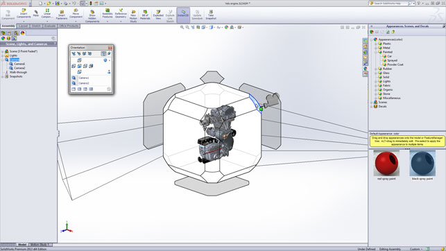
The new View Manipulator gives a quick access to all the usual views
There’s been quite a number of changes to how the system works. While these might not necessarily be brand new, what they do is rationalise existing commands into a set of tools that are more user-friendly and manageable.
A good example is the new view manipulator. While SolidWorks has always had a quick access dialog to commonly used views (front, sides, isometric etc), this steps it up a notch. Now when hitting the spacebar, the view switches the model into a wireframe cube from which standard views can be selected. It also shows any cameras in the scene as well. It’s clean, usable and makes life much easier.
Alongside these user interface updates, this release also sees work done on the configuration tools, which have been a core part of the system for many years. These allow parametrically driven variants of a family of parts or assemblies to be stored within a single data file. This not only saves disk space, but also makes the management of the system easier.
From this point onwards, the system will store the geometry (assuming you switch the toggle) for every configuration without needing to rebuild. It also plays a part in previous release interoperability, which we’ll get onto shortly.
Another generally applicable tool is the ability to visualise the Centre of Gravity in an assembly. Listed in the feature-tree, it can measure, drive parameters or even optimise routines to achieve the required physics.
Modelling tools
This release sees a mix of both new capabilities as well as some reinvention of existing workflows into much smarter features. A good solid example of the latter are the new varying dimension patterns. Have you ever found yourself making a pattern in which a few of the sketches need to be different from the rest? In a typical workflow you would create the pattern, select the ones to skip, then go back and create the different sketches and features from scratch.
These new tools allow you to vary dimensions and locations while creating the pattern. The seed feature is created and you start the pattern command. Then for each instance, you can change its height and/or width, its depth, its spacing or indeed, just skip it. There is even an option to restore a modified instance right in the property manager.

In terms of brand new tools, the one stand out feature has to be Intersect. It wraps up a workflow, which would have previously required multiple features and a lot of geometry wrangling, into one neat feature.
The concept is to use highly complex sets of surfaces, solids and planes and intersect these with other geometry to create a specific form. Intersection geometry is defined and the regions to be removed are then selected. And boom, you’re done. In previous releases, it might have taken multiples of features to create what can now be built in a single, manageable geometry feature.
Conics at last
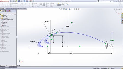
For those working with complex geometry, particularly surface modelling led projects, the introduction of conics is something that many have been waiting for, for a good long while. 2013 brings these into the sketching environment.
Driven by endpoints and rho value, the tools allow the creation of elliptical, parabolic, or hyperbolic curves without the need for splines or equations.
Assembly modelling
Assembly modelling is a key part of every user’s workflow. While some may have relatively simple assemblies, many users are working on ever more complex structures — particularly considering SolidWorks’ strength in machinery design and engineering. The tools within the system have been at a highly advanced state for many years. Smart Mates and the intelligent connection inference tools have made the process of placing individual components much easier than manually knife and forking each constraint.
What the system hasn’t made a good job of (and arguably, any CAD system for that matter) is the placement of multiple components. Yes, if inserting the multiple components of the same part, it is typically fine to use the “push-pin” to keep the command active. But if there is a series of different components, you’ve historically been out of luck.
In 2013, you can select ‘Insert Components’ then browse to a folder and ctrl+select multiple parts to open. What you do from this point determines how they’ll be inserted. If you just click in the graphics area repeatedly, a single instance of each part will be placed where you clicked until all have been placed once.
However, if you hit the push-pin and then double click in the graphics area, all selected parts will be inserted after each double click.
There’s also been work done to improve the placement of inserted parts so that they are closer to existing parts. It’s nice to insert a part and for it not to be feet or metres away from the assembly.
Multiple Explode states
Another upgrade to existing functionality is the ability to hold multiple exploded view states in an assembly.
In previous releases, just a single set of explode sets were possible, from 2013 onwards, these allow you to hold multiples. Of course, while this pays dividends in the assembly environment, but where it really comes into its own is in drawings. Users will now be able to represent multiple exploded states, perhaps to show different assembly tasks or views of a product, all in a single file.
Previous release interop
This has been on the list of most requested features for many years. The truth is that a vast range of users work together sharing SolidWorks data — whether it be different divisions in the same company or between clients and suppliers.
The problem is that not all groups upgrade to the latest release at the same time. Some upgrade immediately, others wait for the first service pack and some even skip releases. This could be driven by corporate policy, IT requirements or just waiting for key plug-ins and partner applications to get updated.

There’s also the fact that in today’s harsh economic environment, some choose to leave subscription entirely and remain with the tools they have. Problems arise when these different things get in the way of a project. If one party has a new version of SolidWorks, the others can’t read the geometry.
As a result, you often find companies (particularly those in a supply chain environment), running multiple versions, which can be a management headache at the very least. Or they rely on a parasolid-based workflow. Neither of which is ideal.
This release sees the introduction of backwards interoperability so that a user with a 2012 Service Pack 5 (due shortly after the shipping of 2013) can open files from SolidWorks 2013. Note that the term used is interoperability, not compatibility.
While we don’t have room to get into the specifics of why older versions of software can’t open newer (it’s a highly complex issue that was recently covered on DEVELOP3D.com), let’s deal with what does work.
Users with SolidWorks 2012 and Service Pack 5 will be able to open 2013 files directly. No save out, no exporting on importing. File/Open. What you get is a read only file with all of the geometry as a b-rep. The metadata is intact, all of the relationships are maintained and all of the configurations are also available.
What you can not do is see or edit the feature geometry — it’s purely the boundary geometry.
Draughting updates
No CAD release is complete without a slew of updates to the tools for creating drawings and documentation. SolidWorks 2013 is no different. While there’s a whole load that are worth exploring, the highlights are on two fronts.
Firstly, Section views have been worked on to make their creation much faster. Essentially, you select the command, pick the view, drag and drop the section line and place the view on the sheet — job done.

The second highlight is the simple fact that the generation of drawing views is now multithreaded. For those working with complex drawing sheets, the ability to have different threads of computation of each view working in parallel, will make things much more efficient.
Of course, this will not only pay dividends in initial creation but will also continue to bare those fruits when design updates are made — or indeed, if DriveWorks and such are being used to automatically generate drawings based on rules.
PhotoView 360
Built by rendering wizards, Luxology (luxology.com), PhotoView 360 has now completely replaced the historical visualisation tools that had been in SolidWorks for a decade or more.
Running in both the modelling window as well as a separate one for user flexibility, the system changes how rendering was traditionally done in SolidWorks.
With greater use of HDR images to provide accurate lighting combined with existing camera and lighting tools, as well as drag and drop materials, it’s seen a massive adoption by users.
This release sees two key new capabilities added. The first is that SolidWorks users can access the custom materials from Luxology’s massive library of materials. Many are available at no cost, but there is a wealth of textures for purchase too.
The second is that support for network rendering has been added. This is relatively simple to set-up and once active, the squares many users will be familiar with on each thread show up as yellow (for a local workstation) and blue (for a core on a cluster). For those working on animations, this is going to be massively productive.
New SolidWorks add-ons
Alongside the core tools in SolidWorks and the new product bundles covering plastics and electrical design, there’s also been upgrades to the home grown add-ons. While the simulation tools are probably the most widely used, the last few releases saw the introduction of both SolidWorks Sustainability for LifeCycle Assessment and SolidWorks Costing.
While not a huge amount has changed for SolidWorks Sustainability, 2013 sees the ability to factor in costing information from the Costing module so that eco-design decisions can be made not only on environmental impact, but also on economic factors.
SolidWorks Costing does not only now include support for multi-body parts, but it can also estimate costs for parts with turned, milled and drilled features.
New bundles
Alongside the updates and enhancements to the core SolidWorks tools, this release also sees the introduction of two new bundles that bring together third party applications to solve very specific needs.
SolidWorks Electrical: The first is SolidWorks Electrical, which combines SolidWorks’ existing tools with ElecPro to fully develop electrical and control systems alongside the mechanical design work. While SolidWorks has had routing tools for sometime, this steps things up a notch. Both in terms of the complexity of electrical data that can be developed but also in terms of interoperability.
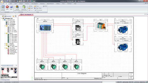
Single and multi-line schematics can be designed with greater integration between the 3D model in SolidWorks and linked to 3D schematics developed by the electrical engineers.
SolidWorks Plastics: The second new add-on is SolidWorks Plastics. Long time users will remember that SolidWorks used to have MoldFlow Xpress for simulating injection mould tools in a very simplistic manner.
Since Autodesk acquired Moldflow a few years ago, this disappeared from the install quite quickly. SolidWorks Plastics isn’t a replacement for this instead, it’s a more thought out, fully developed solution for those working with both injection moulded part design and the production of the associated tooling. Based on the full SimpoeWorks third party add-on, SolidWorks plastics gives a huge range of tools for testing not only part form for manufacturability, but also for proving out tooling, cooling channels etc.
In conclusion
Is SolidWorks 2013 a knock-your-socks-off kind of release? No, the two of us believe that many will think that it isn’t. The general consensus is that it is a stable release with some useful and functional improvements.
The fact is that SolidWorks, like many, has reached a point where the days of huge releases with vast swathes of new functionality are over. What we have now is a highly capable system with a development team that is still refining and improving on existing tools.
This takes two forms. Where workflows are simplified or where they are made more intelligent. The new Intersect tool is the perfect example. It formalises a complex workflow into a clean, simple tool that will benefit many.
With SolidWorks back tracking on it’s next generation product noises (a new mechanical concept modelling system is coming early next year), many in the community are questioning its priorities with regards to the existing platform.
This release shows that the current tools are still being developed and this will continue for a good long period to come. That safe guards thousands of companies’ investments and
should make the whole affair a little less unsettled.
Final word is 2013 is a solid release and there’s plenty to dive into for the vast majority.
About the author
Jeff Mirisola is a design dngineer in Bellevue, Washington and the author of Jeff’s Tool Shed, a blog about SolidWorks specifically and CAD in general. He was educated at the School of Hard Knocks where he recieved a Master of B.S.

Jeff Mirisola
He currently resides in Kirkland, Washington with his three teenage sons, a dog, a cat and 11 fish.
www.jeffmirisola.com
| Product | SolidWorks 2013 |
|---|---|
| Company name | www.SolidWorks.com |
| Price | SolidWorks Premium £6,200 |