Solid Edge. It’s a strange beast of a software application. It’s been on the market for over 20 years now, sold consistently over the years and been through multiple owners.

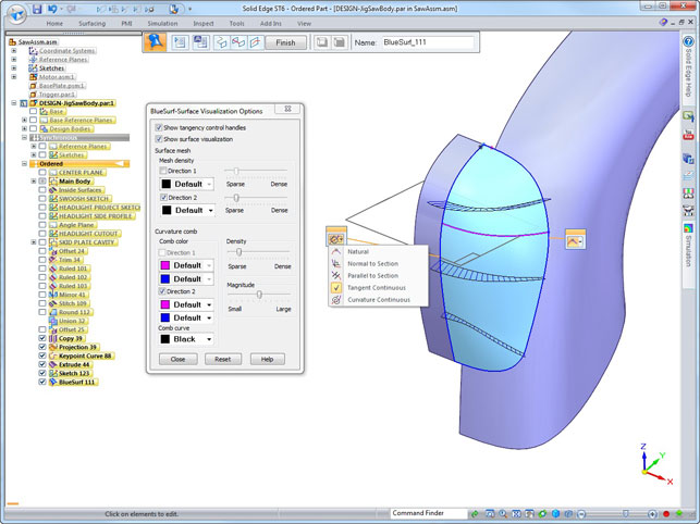
Rapid Blue surface modelling tools are extended with surface curvature continuity control options and additional diagnostic tools
It seems to have found a home at Siemens who has given the application a huge boost (in terms of development and publicity) with the introduction of synchronous technology.
That launch five years ago saw the company revisit its approach to modelling and developed a method based on direct editing that eschewed history-based methods and took things more literally.
Push and pull became order of the day, rather than wrangling with seemingly arcane history trees and feature lists.
Synchronous technology, in the Solid Edge environment, has matured over the last few years, the barriers between the ordered and history based approaches and the new world of dynamic modelling have been broken down and have become better integrated with one another.
User interaction updates
Let’s kick things off with a look at some of the generally applicable updates to the user interface.
The big change is greater control over the size and colour of the all important steering wheel.
You can now use the same steering wheel (think triad with rotational control) for both creation and modification, movement and orientation. Its size can be set to one that’s appropriate for both your monitor resolution and your visual preferences.
There’s also more control over how colour is used in the Solution Manager and error reporting — for the majority of us this makes no difference, but for those with colour-blindness, it’ll prove useful.
Feature & Part modelling
In terms of modelling updates, there’s been a tonne of work done across all manner of existing features (Siemens claims 500 in part modelling alone), but the key updates worth noting are these.
The first is that it’s now possible to propagate synchronous features created in the assembly modelling environment to the root parts.
If you’re wondering where this might be useful, think creating features that span several parts, such as machining treatments, post assembly operations such as hole drilling etc.
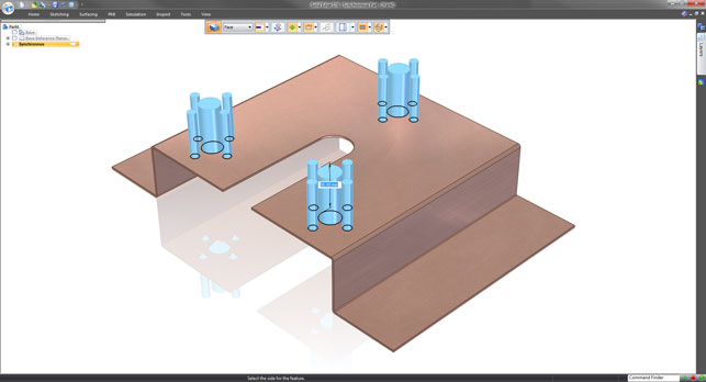
Another, particularly useful for synchronous technology users, is extension work done to the “extrude from planar face” command. This was implemented in ST5, but control was lacking.
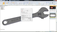
Essentially, it allows you to build geometry from an existing face so that the form matches exactly. ST6 introduces more controls over how the system picks up internal faces whether you want internal loops or not, or indeed, whether you want to just use those internal loops (see figure 2).
Surface modelling
As seems to be a theme in today’s CAD market, where most systems can do pretty much everything,
Solid Edge ST6 is about building on the tools that have been in the system for some time. One area that’s received a lot of attention for this release is surface creation, editing and analysis.
Long term Solid Edge users should be familiar with the Rapid Blue tools introduced back in the early 2000s. These saw the wholesale introduction of surface modelling techniques into what was essentially a solid modelling application.
While the name might seem a little nebulous, it centred on the fact that you create explicit surfaces, based off parametric sketches or exiting model features, but later changes to a surface definition didn’t rely on the order in which the various elements of the surface were constructed. This means you see the dynamic result while editing.
So the obvious question is, if these tools have been in the system for 10 years or more, what has Siemens done to make them more usable or more powerful?
The answer is split across three separate areas. The first is that the system now supports the creation of curvature continuous surfaces.
Whether done from existing model edges or from networks of curves, this should make life one hell of a lot easier for those looking to create more complex forms — whether in consumer products, industrial products (which are increasingly taking on industrial design as a core differentiator) or indeed, in mould and die design.
The options are found in the usual suspects of surface creation — there are new options in the appropriate dialogs. In Solid Edge ST6 several enhancements to the surface control handles for ‘on screen’ edits provides easy control over curvature, magnitude and numeric values.
The first is that there are curvature comb placement tools that are persistent in the creation of the geometry, so inflection points can be identified.
Unfortunately, these only work on the current surface patch, which limits their usefulness if you want to look at the surround geometry as well.
Then the new reflective modelling tools display a graphics-only mirror of the geometry across the working mid-plane, so you can evaluate how the surface set will look across that plane.
There’s also isoline matching tools that allow the user to snap UV lines to match the ‘seed’ face.
Alongside the curvature updates, there have also been a handful of new additions that apply to the creation of more complex geometry. For example, the ability to create a curvature continuous patch surface (including the ability to use guide curve) is now there, there are more tools to help redefine faces (to make them easier to edit) and the ruled surface can sweep a linear cross section along a curve or an existing surface edge.
Sheet metal updates
Solid Edge has always had a reputation for being strong on the sheet metal modelling front — that’s been the case for a decade or more. But as ever, this release shows that with judicious application of some thinking, things can still be improved.
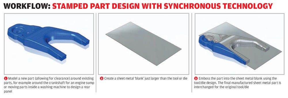
The first example is the new emboss tool. This allows the user to create a forming tool and use that to deform the geometry you need it to.
Once you’ve positioned the former, and a ‘tab’ (or sheet metal feature), the system will offset the geometry around it, perfectly matching the form and maintaining the thin wall required.
While for sheet metal, the use cases are obvious, but this operation also has potential to save time if you’re looking to model cast or forged forms, as it’s often easier to model the shape required and remove it in a single operation. The workflow on the previous page shows how this works.
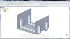
Deformation features can now be added into the flattened state of sheet metal parts, then bent back into shape, retaining them ‘as manufactured state’
Also, for those looking to form material around complex parts or assemblies (think: structural packaging, marine design etc.), this could save a lot of time and effort.
Elsewhere on the sheet metal design front, there’s a new capability to add strengthening features (be they beads, gussets etc.) to a flattened form, then rebend it back into shape with the feature adapted to suit any bends in place (figure 3 shows this perfectly).
The final update that’s worth talking about is an odd one but when you consider its use case, it makes huge sense. You can now add sheet metal features (tabs in particular) to uniformly thick parts.
As most users of mainstream modelling systems will know, to create sheet metal features, it’s usual that the part is defined as such. That forces the system to add in all of the sheet metal parameters (K-factor, bend radii etc.).
But there are also instances where you might want to add in similar features, but can’t because the component isn’t actually intended to be a sheet metal component. Now you can and while it might seem a little esoteric, it’ll prove useful I’m sure.
Sharing learning assets
As a feature, this isn’t the most ground breaking update in ST6, but it does show that Siemens is looking at some new technology to help those starting out with the system.
While I’m sure we’re all more than familiar with YouTube, what the Siemens team has done is integrate the ability to record and upload videos directly from Solid Edge.
It’ll allow you to share your screen and any audio if you chose and shoot it straight into the ether to sit alongside funny cat videos and Russian driving disasters. Now, the more cynical of you might wonder what on earth this is useful for. The answer is threefold.
YouTube for Solid Edge.
Firstly, it allows you to share best practices, either with the great unwashed at large or with a smaller internal design team (you could set up a closed group for your design team).
Secondly, it means you can search for Solid Edge related videos for assist with a problem. If more users use this, add more content, then its value increases. Thirdly, of course, it also increases the visibility of the Solid Edge “brand” online.
Of course, you (or the boss) might not be too keen on this sort of thing, so it can be switched off where necessary/mandated with the system admin tools.
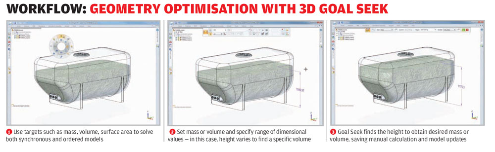
Simulation and optimisation
For the last few years, Siemens has been building in more simulation technology from its wealth of tools elsewhere in its product lines.
Alongside these traditional Finite Element Analysis (FEA)-based simulation tools, it’s also had, for some time, 2D goal seek analysis.
The concept is that you define a goal, define the variables geometrically and have the system optimise those variables to reach the goal. In previous releases, the goal seek tools were restricted to 2D mechanical problems — for specific classes of problems, this was adequate, particularly with mechanism design.
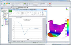
Solid Edge ST6 offers a range of new optimisation tools
With ST6, Siemens has introduced the same concepts which work with 3D geometry. As you can see from our workflow, the set-up is relatively simple (variables, parameters and a goal), but the results can be extremely useful.
Elsewhere on the simulation front using more familiar FEA tools, similar tools are also now available to conduct design optimisation, but to solve those that involved more complex inputs and goals than pure parametric change.
These new Femap-based tools will perform similar geometric optimisation but also take into account other factors, such as finding a balance between deflection and a part’s mass. An application. could be to find the optimal materials thickness for a given strength or weight.
Conclusion
Solid Edge is a curious beast. Not so much the application, but the ecosystem that surrounds it. Technically, the system is mature, strong and innovative. The introduction and subsequent maturing of synchronous technology is progressing very nicely indeed.
What’s also interesting is how the development team is not afraid to revisit existing tools, rework and revitalise them. A case in point in the work done in ST6 to the surface creation tools.
Elsewhere, new thinking, such as enabling the use of intelligent sheet metal features outside of their traditional environment shows that the team is talking to customers, finding their pain points and easing them.
The curiosity centres on the position the system occupies in the 3D design tool market as a whole. For nearly a decade now, I’ve been saying that for the life of me, I can’t work out why Solid Edge isn’t better known, recognised and more widely used.
Perhaps this will change with this release and see Solid Edge flag up on more designers and engineer’s radar? Solid Edge is capable, powerful, modern and in many areas, innovative (I mean that in its truest sense) — never more so than since the introduction of synchronous technology.
It also has a set of tools surrounding it, from simulation through data management and into third party systems, that extend and specialise the system’s capabilities.
That’s a winner in my book.
Solid Edge Insight SP: Sharepoint for CAD Data management
Data management in the mainstream 3D design space is something that’s changing each year. I’ve a suspicion that everyone that needs it is at least on the path to taking on a solution.
After all, we’re at the point where the majority of forward thinking engineering and design organisations have been using 3D design tools for some time — that of course, means a lot of data is being created. Also, we’re in a world where configurable yet modular products are increasingly commonplace.
All in all, the time for data management, even if just amongst the design office, is here and has been for awhile.
Into this environment, Siemens introduced a data management system based on Microsoft’s pretty ubiquitous SharePoint platform, some time ago. This has seen work over the last few years, but with the ST6 release cycle, it’s getting a shot of adrenalin. While Solid Edge Insight is maintained and allows basic storing of documents for collaboration with the team, the new Solid Edge SP takes things further.
While Solid Edge Insight continues as is, the new Solid Edge SP brings a host of new tools to the game. This adds in the management of related data, other office and project documents, change and revision management. All built onto SharePoint which, chances are, you already have.
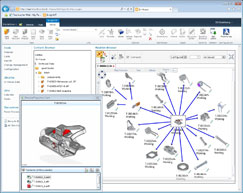
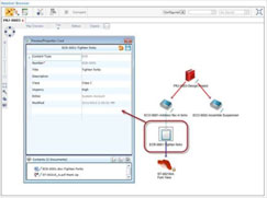
Specific updates for this release include a new preview card that gives you direct access to any related documents from a managed items as well as revisions.
There are new thumbnails of 3D models that are shown in the relation browser. If you’ve not seen this, it’s quite nifty. Instead of the usual hierarchal display of where used/used by search results, this uses a much more graphical approach. Related documents can be seen, how they interact and now, what they look like.
| Product | Solid Edge ST6 |
|---|---|
| Company name | Siemens |
| Price | On application |