The world of metrology and inspection is turning its head towards the world of laser scanning.
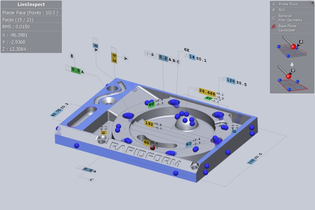
LiveInspect allows the operator to work through probing geometry in a freeform, but still structured manner with direct control of the workstation with the measuring arm and speech feedback
While it’s been accepted industry practice in the reverse engineering world for some time, the metrology market has been reluctant to take advantage of the benefits. This is entirely understandable.
With long established best practices centred on the use of Co-ordinate Measuring Machines (CMM) and decades of traditional methods, the new world of laser scanning has taken some time to gain a foothold.
That said, the benefits are now being understood more widely. Where a CMM or measurement arm gives sparse but highly accurate measurements, a scan-based measurement offsets marginally lower accuracy for a much greater understanding of the entire form of a part.
So while things are changing and many organisations are looking at both processes and workflows, it presents an issue for the software used to capture the various streams of data.
The problems revolve around the simple fact that until recently, separate software was required to capture traditional metrology and scanning-led processes.
Two systems means two lots of licensing, two lots of hardware, two lots of reports and use. Many of the major vendors in the space are looking at this issue, but one that’s ahead of the pack is Korean outfit, Rapidform with its XOV system.
Two processes: one workflow
Rapidform has had XOV in the market for some time, but this release sees its plans to support not only the scan-based metrology workflow, that it has been mastering for years, but to also bring in support for CMM and hard measuring arm devices.
The system is clean and uncluttered with all the icons well presented, which when considering that this is intended for use not only by the metrology specialists, but also on the shopfloor, that’s absolutely essential.
Perhaps the best way to look at what it does is to take a look at how it would be used in that environment and show how the system has been adapted to that use case.
Importing up the nominal
As you’d expect, the first stage is to import the nominal CAD data from the design system.
Even at this first stage, Rapidform has been working to ensure that the process is as efficient as possible. For those working with 3D annotation or PMI (Product Manufacturing Information), then the process is as simple as reading in the native geometry from the CAD system.
Support is available for Siemens NX, Catia V5 and PTC’s Creo. These can be used to define hard inspection points as required.
It’s worth noting that while many systems claim 3D annotation support, Rapidform is amongst the few that support the gamut of the 3D GD&T (Geometric dimensioning and tolerancing) from the ASME Y14.41 standard.
Of course, not everyone is using one of these systems or stores 3D annotations as part of the manufacturing prep process.
To assist those users, Rapidform uses intelligent feature recognition to find faces, cylinders and other common reference geometry automatically from imported geometry — removing the need to define it manually after import.
Nominal to physical alignment
This release sees the introduction of LiveInpsect — a new way of working for existing XOV users.
The concept is that rather than following a prescribed set of inspection points, clicking in very specific positions in a predefined order, the system allows more freedom.
In the first instance, this is used to align the part on the inspection table, machine bed or elsewhere to the CAD nominal.
To align a part, once a geometry entity (plane, face, cylinder) from the CAD geometry on screen has been selected (note, the system allows control of the software using your measurement arm), the user can then start probing the correlating geometry on the physical part.
As you do this, the system automatically adjusts to ensure that the nominal is matched to the physical coordinates of the part.
It’s at the point where the nominal data is prepared and the hard probe measurements are defined that the new release’s tools really kick in.
Hard probing
Assuming that datums, references and inspection points are already defined, the system now allows the user to start probing the part.
As the measurement arm is moved, the display updates and shows where it’s located in respect to the part on screen. As said before, XOV doesn’t enforce a specific order of inspection, but is more free.
The system displays all the features needed to measure and colour codes them on the CAD nominal. As each feature is probed, it “checks them off” as they’re completed and stops highlighting them.
It also gives a “remaining tasks” read out making the user instantly aware of what needs to be done.
What’s also interesting is how the system gives immediate feedback about the nature of the physical part being measured in terms of an RMS error of measurements vs the idealised shape.
If the user is only using a hard probing inspection process, then at this point they would move onto the reporting stage. But if there is scanning hardware to hand, it might as well as be taken advantage of, so let’s look at how that works with LiveInspect.
Scanning the physical
Now, with separate tools it’s at this point that a different application would need to be fired up and the alignment process repeated, causing a lot of work.

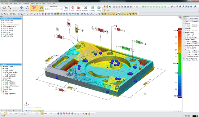
With XOV, the user instead switches to using a scanner and starts to scan the part. Again, the feedback is instant, with the system quickly processing the captured points and displaying a colour-coded representation of the points against the user’s nominal CAD geometry.
Every pass of the scanner (it supports all the leading manufacturers) provides more data about the deviation from the nominal on the part, across a much wider spectrum of the part’s form.
If two separate devices are being used, the only thing you need to do is establish a common coordinate system to work in.
This can be done inside XOV. For example, the user can do a 3-2-1 alignment with the probe, and do the same 3-2-1 alignment with the point cloud, and they’ll then be aligned to the CAD model or same origin.
Reporting
Despite the user scanning and probing with different devices and processes, XOV has a wealth of tools for reporting.
In the immediate instance, when the process is complete, reports can be set-up (using a built in studio environment) and spat out into the right format, whether that’s Excel, PDF, Word etc. The system includes all manner of reporting and analysis tools.
Of course, it supports the reporting on points measured using the GD & T tools, but also includes more advanced options such as cross section analysis, silhouette deviation as well as more specialised tools like boundary deviation for trimmed sheet metal components or virtual edge detection for the aerospace and turbo machinery industry.
All of these methods can be integrated into standard reports, images automatically captured and all the data tabulated.
Rinse and repeat
If the user is working with one-off manufacturing, chances are an inspection process will be carried out, the report created according to a predefined template and, apart from a few on-the-fly tweaks, that’s it.
But if they are working on series production, then XOV has some interesting tools up its sleeve.
The whole process we’ve just been through is captured in a history file. This can even be inspected if needed. But the real benefi t is that the same process can be repeated and another part off the production line inspected.
While this isn’t anything particularly out of the ordinary for today’s inspection software, the flexible, more freeform manner in which the next run is done, most certainly is.
XOV also includes a set of batch processing tools, which means that multiple measurement sessions can be captured, then post processed in one go. As a result, the operators are freed up to conduct the work and then have a workstation chunk away to output the reports and capture the usable data.
XOV also comes with trend analysis tools that can give those responsible with overseas production greater visibility of potential problems.
Conclusion
When you consider that it wouldn’t typically be one person, or indeed, done on a single manufacturing site, then the ability to capture an inspection routine, standardise and deploy it, without the constrictions of a fully prescribed process, is incredibly powerful.
The nature of the Rapidform XOV3 system means that processes can be formalised and distributed, but with enough flexibility built in to account for different set-ups, hardware and user preferences.
Ultimately, the adoption of scanning processes alongside more traditional and established inspection methods is going to take time. There’s decades of entrenched behaviour to not so much change, but rather expand and bring these newer devices and their benefits into corporate working practices.
The benefits are clear, in that you can gain a much better understanding of the state of the whole part, rather than specific areas.
Truth is that both approaches have their benefits and pitfalls. The key is to balance them and find what fits best. Part of that means that you’ll need to ensure your software supports not only the hardware you choose, but also the processes you put in place.
Rapidform’s XOV does both well. It does it in an environment that allows the operator to work as they prefer, but allows the company to not only standardise inspection routines, but also gain a much better insight into their production processes.
It’s truly first class stuff.
| Product | Rapidform XOV3 |
|---|---|
| Company name | Rapidform |
| Price | from £14,000 |