Over the past few years much of the coverage about Siemens’ flagship NX system has centred on HD-PLM and Synchronous Technology, and there’s been little written about the product’s long standing roots in the manufacturing industry.

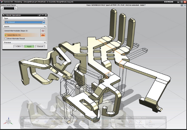
Unbend is used to unfold linear bends. For over-bends, NX provides parameters to control the bend radius and bend region
Today, NX stands as one of a handful of truly integrated CAD/CAM systems, which allows an organisation to take data from conceptualisation, through design and engineering and into the business of manufacturing and production with a range of technology for tooling design, NC programming and beyond.
In NX 7 the system received a lot of development effort in Progressive Die Design and it’s this that will be the focus of this review.
Unfolding and unforming
As with all Progressive Die Design tools, the starting point is the parts that need to be manufactured.
These will typically be complex parts of a uniform thickness with a myriad of folded, bent, punched and stamped features. Even at this root level, it’s clear that Siemens has an advantage over many mainstream tools in its pure geometry wrangling tools.
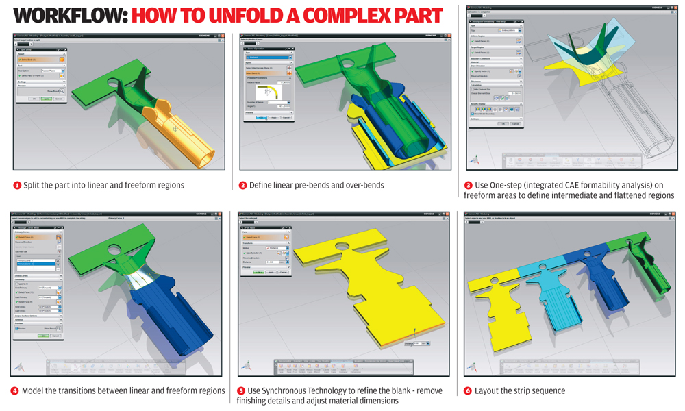
Progressive Die design works in a reversed process, starting with the final shape, then working backwards, unfolding the form until a flat blank is reached. Siemens has integrated a host of tools to do this, either using an automated process or, for the more difficult components, allowing the user to manually flatten out each complex bend or stamped form.
Straight break parts are arguably the easiest to move quickly through the unforming process, as their bends are typically linear and relatively simple in nature. Thanks to Synchronous Technology the system can work through both native and imported data and will quickly identify all of the bends in the part.
The user then creates instance after instance and works out the order in which the bends will be created in the strip. Each is an interlinked instance of the previous stage, so changes and modifications can very quickly be propagated through.
More complex parts require manual intervention, but again, the power of NX’s geometry wrangling tools and its simulation capabilities, all come into play here.
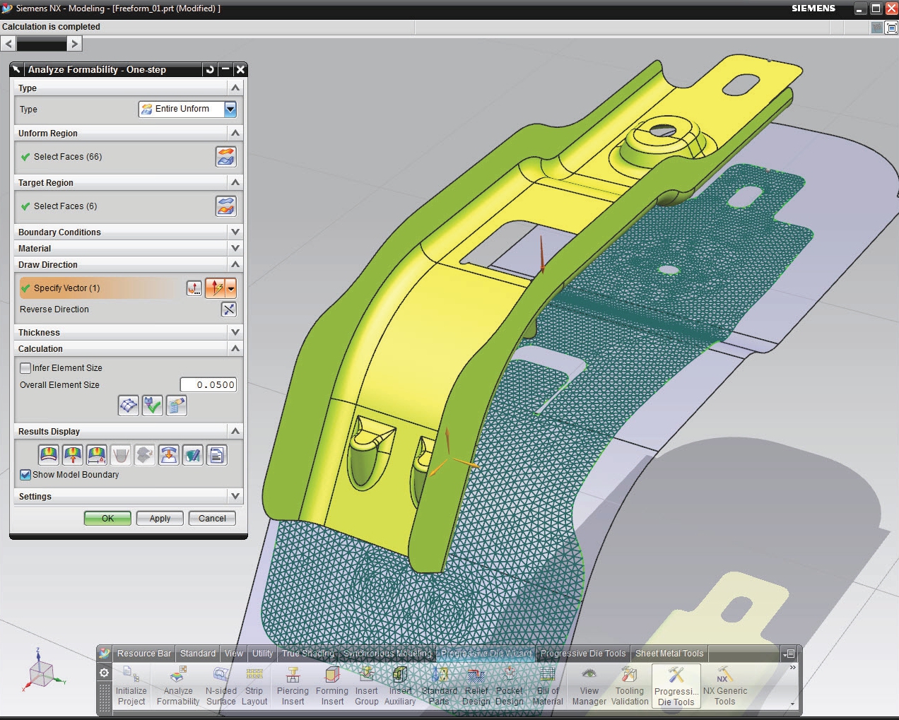
When working up the flattened or intermediary stages of a complex stamped form, the user not only needs to be able to analyse the resultant shape (from which the form is created), but also ensure that there isn’t excessive strain placed on the sheet material or, even worse, tearing.
The system has a lot of specialist tools built into to assist with formability analysis. These use FEA like techniques to create an accurate and viable blank in terms of manufacturability.
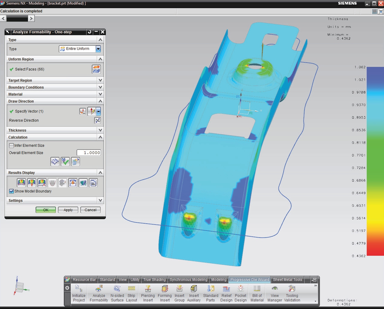
Essentially, the system creates a mesh of the mid-surface of the part in question (though the outer or inner surface can also be used). This is then adapted to a surface that represents the ideal surface form that the part is flattened onto. The mesh allows the distortion of the material to be tracked and used as the basis for simulation.
Following this the system runs through a simulation to get from one to the other. All of the analysis can be documented using HTMLbased reports to record how decisions were made and to put them into context.
For many parts the approach used (either straight break or freeform) won’t be as clear cut and here the system allows users to mix and match the techniques where needed. It may be the case that a part requires one complex forming operation to be carried out, and the straight break, feature-driven tools can be used for the rest.
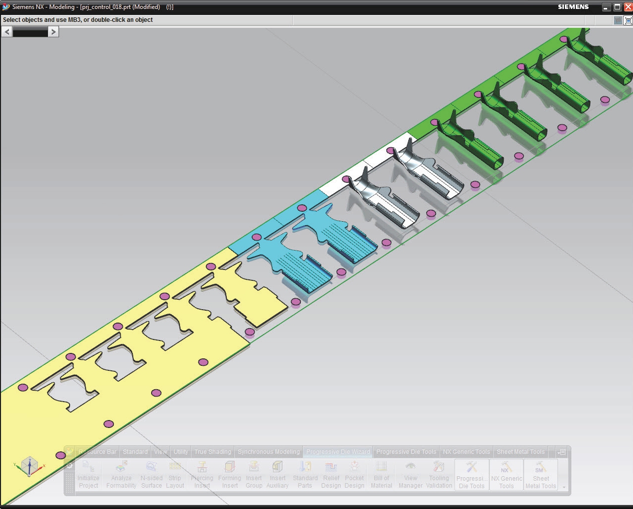
Once the part stages are complete the next step is to move into creating a strip layout which better represents the form of the sheet material as it moves through the die.
This is easy and requires very little in the way of interactive input unless you need to introduce special features such as notches for strip location, overlaps and overcuts for trimming purposes.
One of the most critical features in these times of harsh economic pressure is the ability to maximise material usage (or to put it another way, to minimise material wastage). The system can display a perrsistent material usage meter using colour to show unused stock.
This allows the user to play with the distances and swap around intermediate stages to help maximise the amount of parts that can be made from the die, without sacrificing quality or manufacturability.
Die base design
The next stage is to create the die base. As with almost all modern mould or die related applications, NX’s Progressive Die Design tools are catalogue-based.
This allows users to very quickly select standard component stacks from preferred vendors. For those looking to custom-build a tool then all of NX’s modelling functionality is at hand, but it’s probably more effective to adapt existing models, so they retain their intelligence.
Alongside the plate stacks, there is a full library of components, including their inherent mounting features such as drilling cycles, and taps. Once in place, it’s a case of moving on to creating the features that actually form the components that are being worked on.

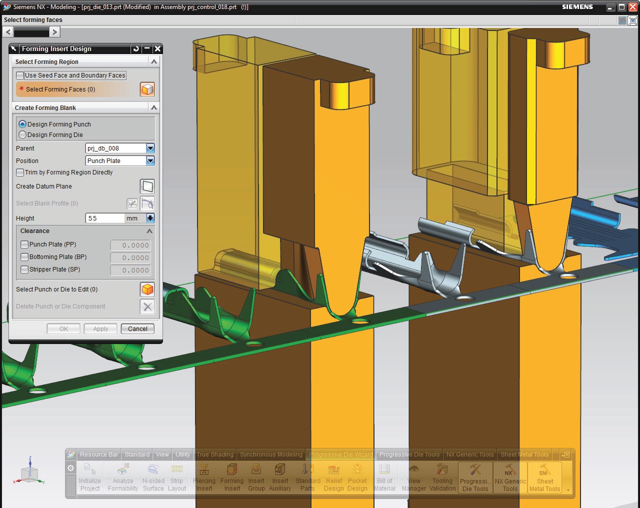
At this point it’s important that the user is working with an intelligent model. While experienced users may have a good idea of where component clashes may occur, it’s not until the hard geometry for the various piercing, punching, bending and forming inserts are defined, that they will get a concrete idea of where things are heading.
NX includes template-driven operations for creating these types of features. These include the extraction of the faces that represent the cut or forming surface, the extension of those faces and the creation of the shank, any additional components (such as the heel, ramps, flanges etc) or the associated cut-outs or reliefs for the insert once this is complete.
It’ll even add in a little clearance to ensure it’s possible to remove the inserts where needed, and combine seemingly separate inserts onto a single plate and much more.
Where possible and applicable, these can be reused across several operations. For example, if there are common holes or other features to be punched, they can be copied and reused – all the while, linking back to the original data.
This is perhaps the biggest benefit of using a system like NX Progressive Die Design. Whether starting with native data or imported ‘dumb’ geometry, everything you do is associative. It becomes much easier to accommodate design change and make adjustments. Then in subsequent projects, data can be reused.
Into production
Because the software is based on the NX platform, the tools are able to pull in additional capabilities that exist within the system. One excellent example is the ability to simulate the movement of the die.
This helps ensure that the various components don’t clash or interfere once assembled and that the die works as required. Of course, once the die design is complete, all the kinks are worked out and things are ready, the next stage is to start the preparation for production.

In the first instance this can be the creation of the toolpaths for machining the die plates, the punches and inserts. NX has an enviable reputation as a CAM system and has many strengths – not only in terms of production machining of plates by milling/drilling cycles or wire EDM, but also in terms of machining the inserts.
These can often be complex requiring-5 axis machining for successful and efficient creation. Alongside the machining considerations, it’s also worth noting the wealth of tools available to assist with documenting the die – not only in terms of manufacturing, but also in terms of assembly, installation and maintenance.
Intelligence & design change
We’re all used to design change being part of our workflow – it’s a fact of life and is as much a part of the engineer’s working day as anything else.
When it comes down to progressive die design, however, design change can be a nightmare – unless the system has been designed to handle it efficiently. This has been built into NX so it can be done from the very start of a project – and by that I mean, from the Request For Quotation (RFQ) stage.
Most typical die design projects are quoted on a rough estimate of how complex the tooling is, but particularly for those working in a supply chain this is commonly offset against the margins made on unit price for the resultant parts. That can give a real headache.
If you underquote on the tooling, perhaps as a result of miscalculating how many stages and how quickly the parts can be produced, then the chances are that you’ll have got the unit costs wrong as well. While a component might appear ‘easy’ to manufacture, anyone with experience in the field will tell you that simple mistakes can be the most costly – and with today’s economic pressures, that can be a costly mistake too many.
By allowing users to take a component from part geometry, through unfolding and strip layout in a very short space of time and then even into die base layout, the system gives a real opportunity to valuate the process of producing the mould and components in the same timeframe that many users might take just to do the unfolding.
Then with a much clearer idea of the complexity of the task at hand, that information can be fed into the quotation process to help ensure competitiveness is based on fact, rather than guess work and estimation.
Moving on from RFQ and into production preparation, the tools in NX allow the die layout to be adjusted very efficiently.
Because everything links back to both the original part and the subsequent strip layout, the system allows users to drag and drop stages, adapt folds, bends and punches to not only ensure the required form is created, but also so it makes the most efficient use of material and that the die can work throughout the required period.
Conclusion
NX Progressive Die Design, when considered as a set of add-ons for NX, is an excellent example of what can happen when a strong and capable platform is combined with a huge range of expert-led specialised tools.
Progressive Die Design is a very complex process, both in terms of the complexity of the product (the die), and the business of manufacturing those components.
With economic pressures never being higher, the ability to not only turnaround quotes, but also the final product, in short timeframes is absolutely essential. The chances are that if you’re looking for a tool like this, then you’re working in a sub-contract environment and that can only make things more critical.
Excessive material scrap has to be minimised, the ability to iterate a die design to accommodate new design changes is key and you need to know that you’re working on a profitable project and meeting customer demands. Of course, the same is true for those working in-house manufacturing projects.
In summary Siemens PLM has managed to build an environment that brings specialist knowledge and automation to the fore, supporting the industry it’s meant to serve and providing a functionally rich set of tools to take a part from geometry, through unfolding and strip layout, into die design and machining, in as short of a space of time as is possible.
But within that idealised automated workflow, it’s also possible for the manufacturing engineer to dive in and fine tune, reuse and adapt data where required. And we can’t ask much more, can we?
| Product | NX Progressive Die Design |
|---|---|
| Company name | Siemens PLM |
| Price | on application |