Ministry of sound

Share this article:
|

20 March 2009

Process types: Design and Prototype

Legendary audio visual manufacturer Bang and Olufsen has just unveiled its latest innovation, the BeoSound 5. Frances Corbet talked to its designers about how prototyping played a key role throughout the development process

There is an aura that surrounds Bang and Olufsen’s products – it’s almost as though they have been touched by magic, whether it’s a CD player that opens with the wave of a hand or a plasma screen TV that swivels to adjust itself to your viewing position.

Built on more than 80 years of Danish craftsmanship and innovation the audio visual manufacturer is renowned for its distinctive range of televisions, music systems, loudspeakers and multimedia products. More recently it has added mobile phones to its portfolio, plus premium sound systems for automotive companies including Audi and Aston Martin. Bang and Olufsen’s products may come with a rather hefty price tag but customers are willing to spend more on technologically excellent products that come in a stylish package.

Towards the end of last year, under a shroud of mystery, the company unveiled a new product - BeoSound 5, a high-quality digital audio player that is intended to bridge the gap between its high-end hi-fi systems and those that store music digitally. At the heart of the system is the BeoSound 5 controller - a 2.65kg tabletop or wall mounted remote that features a 10.4-inch LCD display and an aluminium navigation wheel. The wheel allows users to scroll swiftly through their music collection as well as over 8,000 Internet radio stations with every move mirrored on the screen in an array of colours, fonts and choreographed graphic displays.

BeoSound 5 runs on B&O’s new intelligent playlist system - ‘More of the Same’ or MOTS. As the company describes it, playing a song is like planting a seed - whenever you start playing your favourite music, MOTS automatically scans your library and finds similar tracks based on parameters such as rhythm, syncopation, key tonality and vocal harmonies. Also included in the package is the BeoMaster 5, a discrete black box that provides 500GB of storage and all the electronics required to drive the system.

BeoSound 5 started its life in B&O’s ‘IdeaLab’ as a user interface exploration. IdeaLab was set up in 2004 as a new department to look specifically at digital concepts and acted as a supplement to the existing design department IdeaLand. These two departments have since merged to become IdeaFactory. Oliver Wallington was one of the early members of the IdeaLab department. Having graduated in Industrial Design from Brunel University he spent eleven years working as a design contractor for LEGO, amongst other companies, and four years ago moved to Struer, Denmark, where he took up the position of concept and prototype developer at B&O. “My primary role has been looking at function and product concepts specifically in the digital technology area. This has naturally led into some user interface work,” he explains. “My projects are a mix of ‘briefs’ from the company and my own initiatives.

“Its hard to define a concrete process as this very much depends on the project, some are very conceptual where we look at trends in user behaviour whereas others could be the actual function and interface on next year’s DVB module.”

Cue the music

Through his exploration and concept work into digital platforms and connections it became apparent to Wallington that due to the huge amount of content that could potentially be held in hard drives, new navigation solutions for audio/video (AV) products would be required. However, it was not merely a case of trying to improve on existing solutions; he wanted to completely reconsider navigation due to the volume of content. “At the same time we realised that B&O needed to be more confident in the screen space, the graphic and animation quality of our pixels did not match that of our physical design. A natural step in this process was to look at on screen menus/navigation,” adds Wallington.

So, he started looking at literal connections between moving mechanics and graphics. In order to explore this more fully he created a basic prototype of a wheel interface that could be attached to the back of a tablet PC. “With the interface we were looking at the on-screen graphics being animated in a way that the movements correspond directly to the mechanical movement of the physical wheels. The idea is that the graphics appear to be physically connected in some way to the interface, thereby giving an overall more mechanical feel,” explains Wallington. “B&O has a long tradition in mechanical interfaces and mechanically moving parts so we considered it interesting if the screen graphics could continue this story.”

Using this prototyped hardware, Wallington and his team experimented with many different kinds of interactions, graphic layouts and functions. They also made further models using cardboard, LEGO and computer parts, and optimised their software for these. “Although these prototypes are unlikely to win any design prizes, they can tell you a great deal about what is needed to ensure good functionality,” he adds.

It was only then that Wallington started to consider where this could be applied and for a number of reasons decided to focus on developing a home audio product. This decision was also influenced by the work that was being carried out by the MOTS development team who were actually sharing Wallington’s workspace in IdeaLab. “We were playing with some ideas of what we could use the interface for and a strong direction was audio. There were also many people talking about MOTS however, there had been no explorations of a product interface for it. As we were making interface prototypes as a part of exploring the graphic/mechanic connection we thought we might as well add MOTS functionality and see how that would affect the navigation,” explains Wallington.

The prototyping department then made a better hardware platform for Wallington and his team who continued making user interface iterations for it using Adobe Director. “While the interface could potentially be used to control many things we wanted to purely focus on digital audio. Similarly, we explored its position and use in day to day scenarios with a remote control,” says Wallington. “We wanted the product to have a very clear and definite purpose and we wanted to develop a known product category rather than create a new one.”

It was only at this point that the concept was presented to top management who agreed that it could be made into a B&O product. The designer Anders Hermansen, who had previously worked on B&O’s earset and earphone products, then came onboard. “The designer was concerned with the use of buttons on the early prototypes to select between navigation options,” says Wallington. “He perceived an issue in two handed operation as the user may have a glass of wine in one hand. Due to this the navigation options were then selected by a lever under the wheel that points to the option on screen. This also gave a good interface benefit as the physical buttons could constrain us in future updates and the lever is far more flexible.” In developing this lever idea some new test prototypes were made using smashed up joysticks to simulate the lever input.

Working in harmony

Together with the designer a team of concept and user interface developers, mechanical and electrical engineers, software developers, production planners and many others became involved in the project. “We were trying to speed things up by working in parallel and taking in all relevant inputs into account in the very early stages of the development,” explains Jorgen Daucke, concept manager in IdeaFactory. “It was a tough job because we had to optimise mechanics, optical encoding, player software at the same time as finding the right design expression and make it hang together with moving graphics on the screen.

beosound 5

Bang and Olufsen’s mechanical designers use Pro/Engineer and take advantage of a number of features including Mechanica, Plastic Advisor and BMX (Behavioural Modelling eXtension). For calculations they use Mathcad and Windchill for data management

“The job was to make the covers and tags stick to the wheel in a convincing one-to-one manner. In my opinion we succeeded in not making a display with a wheel - we made a wheel with a display instead.”

This was very much a prototype-focussed project and having a small prototype department in-house was hugely beneficial in executing one off models in order to gain hands on experience. “The interplay between Pro/Engineer and fast [rapid] prototyping is very helpful, but from a concept manager’s viewpoint it can never be fast enough,” comments Daucke. “When you build models you have to have a clear focus as to what they must show - is it a design model, an interface prototype, a display/front glass model, a tactile response model?

“If you try to build it all together in one model during the early stages of development complexities will arise and delays will occur. The trick is to keep models simple and independent if possible.
As much of the project had to happen in parallel the various prototypes also added communication between all those involved. “I would argue that the development of the product was very centred around prototypes - the nature of the product requires function, interface, design and mechanics to hang together and a combined prototype was the best way to communicate,” he says.

Closing notes

Once the designer had refined his design and the user interface team had completed the final function space the project was then handed over to the R&D department for more detailed development. From here the BeoSound 5 went to manufacture, was revealed to the public last November and will be available to buy from one of B&O’s 1,200 exclusive retail stores starting this month. The company obviously has high hopes for this product with B&O’s CEO Kalle Hvidt Nielsen referring to it as a “breakthough product” at the launch.

“I think it is fair for Kalle to describe the BeoSound 5 as a breakthrough product, there really is nothing else like it,” says Wallington. “It has really challenged the conception that the home stereo product position is invalid due to computers and media centres.

“We feel that it is very much a living room/home product that has managed to take the benefits from the PC environment without the PC tone of voice. One of the best compliments I have heard as a developer on this product was that it is “very B&O”, and that is hard to describe.”

However, like many companies B&O has also been affected by the current global economic slowdown. As part of its Pole Position strategy plan announced last October, the company is currently streamlining its product development to make it possible to increase the number of product launches. Nielsen argues that stronger product concepts are needed in B&O stores to improve turnover and he is confident that these are already in the pipeline. However, this has meant that as many as 220 employees in Denmark and abroad have had to be laid off. Although regrettable, Nielsen said in a statement released during January that B&O has no choice but to adapt to changes in the market and the current economic situation.

However, despite the climate Wallington says that B&O is still one of the most exciting places to work at the moment from a concept viewpoint. He feels that the whole AV category is undergoing a major shift due to digital technology and this presents an opportunity for B&O. “The things that originally motivated me to work for the company were the quality and the distribution chain. If you are working a lot with ideas you want to see them made well. Also, the Bang & Olufsen shops mean you can come up with genuinely new product concepts as there is a space and knowledgeable staff to introduce and communicate these,” says Wallington.

“These are still key for me in terms of working for the company however after a few years here I would also add that it is a company that respects individuals, allows them to grow and define their own role.”

www.bang-olufsen.com

Comments on this article:

Up periscope

Share this article:
|

16 March 2009

Process types: Collaborate, Design, Manufacture and Prototype

Kent Periscopes has been designing with military precision for over 75 years, but as the battlefield changes it has had to adapt to keep its manoeuvres ahead of the field

Short notice, low volume requests for military equipment require all the precision and durability of a piece of kit with years of planning, but are often needed in a fraction of the time. One of the company’s most recent projects was a periscope for an armoured vehicle.
To supply 25 castings in just three weeks the firm from St. Asaph, Denbighshire, turned to rapid prototyping, tooling and manufacturing specialist ARRK.

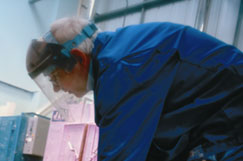
A total of 25 periscope castings were manufactured

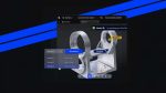
Kent Periscopes built up its 3D CAD designs in SolidWorks and AutoCAD, and then passed the data to ARRK, who moved the job to its in-house foundry based in Gloucester that it uses to cast in aluminium or zinc. The next step involved producing a standard stereolithography model, from which patternmakers and foundrymen produced a tool to obtain the casts.

Short notice, low volume requests for military equipment require all the precision and durability of a piece of kit with years of planning, but are often needed in a fraction of the time

The urgent operation equipment, designed for immediate use in Afghanistan, was to be in a finished condition including inserts, alochrome and paint. This was further enhanced down to the last details of being sprayed with a non infrared detection coating to help hide from night imaging devices.
By having the periscopes speedily put together through the in house process, a lot of time was saved over the usual process – a typical investment casting process can take up to ten weeks.

Foundry manager at ARRK PDG John Hill, said: “Using ARRK’s RPM service to deliver aluminium castings the client is able to validate the original SLA master very quickly before committing to further downstream processes,” adding that having SLA and foundry specialists working together has other benefits. “They are able to advise on the manufacturability of the client’s design so that if any modifications are required it is done at this stage rather than later where the client will have lost valuable time and money.”

The final products have already been shipped out to troops, ready to be fitted to an undisclosed type of armoured vehicle for immediate action in the ultimate testing ground – military action in Afghanistan.
www.kentperiscopes.co.uk / www.arrkeurope.com


Comments on this article:

Fancy footwork

Share this article:
|

13 March 2009

Process type: Design

Women’s footwear is full of complex and colourful designs, however, the Eamz shoes are a little more eye-catching due to their intricate heel.

Produced by United Nude, a company that works with designers from all industries to produce original shoe designs, the shoe has a horizontal heal inspired by the world of furniture deign.

Referencing the classic Eames chair, founder of United Nude and designer Rem D Koolhaas wanted it to embody the same sense of cool. “It’s an ode to them, saying that the Eames chair is so cool and so clean in its design that you can create a shoe from the concept of it,” says Rem.

A classic in the making? United Nude’s Eamz pump in red patent leather

“I think that some women see the shoe and are automatically scared of it.  Others see it as an opportunity to wear something different and get noticed. I mean, isn’t that why women buy expensive shoes in the first place?”

Developed with the assistance of Dutch master shoe-maker René van den Berg, the shoe took a lot of designing. “I drew the heel myself in AutoCAD since I am a trained architect and this is the software that I’ve always used and feel most comfortable with,” explains Rem, adding, “Since the Mono Eamz has a fully moulded upper, you’re dealing with double curved surfaces and we use 3D software like Rhino or Pro/E and Symatron to make high-level moulds.”

Strength testing was done the old fashioned way by having a human take to the floor in a pair of the heels, which should have proved a nerve wracking experience. However, rapid prototyping was involved throughout the mould making process to reverse engineer any changes. “With each round we make improvements and typically a new shoe style will use about three or four rounds of prototyping,” says Rem, before disclosing his next design. “I am currently working on a shoe that I used NextEngine’s 3D scanner to help me in the development process and this shoe required seven prototypes.”

In the case of the Eamz, manufacturing such a design proved a challenge, having to have the part manufactured and fitted in a motorcycle factory. Rem sees this as another accomplishment between the different worlds of design. “Traditional shoe companies don’t utilise this type of part in making shoes, so we had to find a supplier and a factory that could do a heel that was beyond the realm of shoe-making,” enthuses Rem, “It’s a really good example of industrial design because it’s making a cross-over between different industrial disciplines.”

From his background in architecture Rem seems happy to work in CAD when designing footwear, yet that doesn’t mean it isn’t still a challenge. The challenge is “to get something ultimately that is very industrial in its origin, but that has a very manually sculpted feel to it in the end. You can have something that is so clever and smooth but that is also elegant and sexy and well proportioned.”

www.unitednude.com

Comments on this article:

Wing beater

Share this article:
|

13 March 2009

Process type: Simulate

Computational Fluid Dynamics (CFD) is speeding development of an unmanned aircraft which is able to carry bigger payloads and take off on shorter runwaysthan traditional planes, writes Joseph Kummer, Propulsive Wing

For over a century mankind has devoted substantial resources toward achieving and improving flight. With the yearly threat of major wildfires and the ongoing conflicts in the Middle East as its primary focus, Propulsive Wing, LLC is developing unmanned aerial vehicle solutions for both domestic fire fighting support and military applications, covering a wide range of missions.

The Propulsive Wing is a completely new class of aircraft based on the integration of a cross-flow fan into the trailing edge of an airplane wing. The project began at Syracuse University with funding from NASA Glenn Research Center, and the technology is currently patent pending. Propulsive Wing LLC was founded to continue development and commercialize the platform as an unmanned airplane. Propulsive Wing is partnering with Elbridge, New York based engineering firm Allred & Associates, Inc. to accelerate this process.

Closeup of the polyhedral mesh around the cross flow fan

With its unique design, for a given wingspan, Propulsive Wings are able to carry up to three times the payload weight and ten times the internal payload volume of conventional systems. For this reason, the company calls its aircraft an aerial utility vehicle, or AUV for short. Propulsive Wing AUVs require shorter runways for take-off and landing (due to their extremely high lifting capability), generate low noise, and offer a high degree of user safety due to the elimination of external rotating propellers. This platform is applicable to many aircraft sizes ranging from small to large, unmanned and manned military, experimental, private and commercial passenger and cargo planes.

CFD was used throughout the design process to drive both aerodynamic and manufacturing decisions. For the current PW-4 prototype, which is currently undergoing flight-testing, the entire airframe was designed in CAD and modelled using STAR-CCM+ before fabrication even began. The ability of the application to import a CAD model and create a new computational mesh allowed for multiple design iterations to be completed within a short timescale.

In addition to complete aircraft simulations of the PW-4 prototype, CFD was also extensively used to simulate sub-systems. In the design of the cross-flow fan propulsion system, simulation results were used to optimize the blade and housing geometry. Using CFD, Propulsive Wing designed a custom carbon-fibre cross-flow fan with excellent mechanical and aerodynamic performance.

At the next level, simulations were performed to investigate the integration of the cross-flow fan within a propulsive airfoil. These studies looked at the effect of propulsive airfoil design parameters, for example fan speed and sizing, duct inlet and outlet locations, and exhaust angle, on lift, drag, and pitching moment. Also, power requirements in various configurations were calculated.

Full 3D unsteady simulations investigated the performance of the entire airplane. Understanding pitch stability characteristics and creation of a stable aircraft was a major technical hurdle. The Propulsive Wing configuration inherently involves complex coupling between the propulsion system and the wing pressure distribution, and can result in significant variations in pitching moment.

For example, if fan speed is increased, this in turn increases the flow rate, the result is not only higher thrust, but, depending on the exhaust angle, changes the pitch-up or pitch-down tendency of the airplane. Simultaneously, however, the fan also produces greater suction at the air inlet, which alters the pressure distribution on the wing surface, while creating a nose-up reaction due to the direction of rotation. Using STAR-CCM+, Propulsive Wing was able to successfully understand these relationships and create a stable flying aircraft.

The Propulsive Wing fits several niche applications where there currently is no solution. One is large payload, short duration sensor deployment for the military. Also, as the platform scales up, the large cargo and short takeoff and landing capabilities lend the AUV to missions where food, water, or other supplies need to be transported to remote or high altitude locations, both for military, as well as civilian emergency relief.

In addition to military use, one of the primary missions at Propulsive Wing is to develop the aircraft into a frontline component in the suppression of wildfires, which endanger people, wildlife, and agriculture. The goal is to supplement the use of large tanker-sized aircraft with swarms of smaller unmanned drones that will each drop up to 100kg of water or fire-retardant chemicals.

The short-field capability, compact size, and large cargo-carrying ability of the Propulsive Wing units, will allow rapid deployment from remote areas to help extinguish the thousands of small wildfires reported each year before they grow larger.

www.cd-adapco.com / www.propulsivewing.com


Comments on this article:

Life changing design

Share this article:
|

13 March 2009

Process types: Design, Manufacture and Simulate

Stephen Holmes takes a closer look at the cutting edge design projects going on in the world of medical science

Touch and go

In the world of prosthetics a lot can be hidden behind everyday clothing - shoes over feet, trousers over legs - but a prosthetic hand has to leave its user feeling confident.

Touch Bionics of Edinburgh has created the i-LIMB Hand, a prosthetic device with five individually powered digits that looks and acts like a real human hand. Developed using cutting-edge mechanical engineering techniques and manufactured using high-strength plastics, the designers originally approached Paragon Rapid Technologies to develop the mechanical element of the i-LIMB Hand through rapid prototyping.

A further step was taken when looking for materials to produce the i-SKIN, a thin layer of semi-transparent material to accurately wrap to every contour of the hand and move and flex in the same way that human skin does. Paragon was provided with a complete CAD model of the i-LIMB Skin and set about testing various rubbers, eventually arriving at a silicone covering, produced from a stereolithography master pattern CNC machined from Aluminium.

Although available in numerous skin tones, a popular version of the final covering is semi transparent, owing to the love of some patients of the robotic nature of the hand and their desire to wear it without a cosmesis glove. The end result is a futuristic appearance to an already technically life-like bionic human hand.

www.touchbionics.com

Breathe easy

Inhaler

Featuring an integrated dose by dose counter 3M’s new inhaler is designed to give users more confidence about when the unit is about to run out

A common companion to most asthma and chronic obstructive pulmonary disease sufferers, the pressurised metered dose inhaler (pMDI) was invented by Riker Laboratories in 1956. That company is now part of 3M, who has taken the design a step further by introducing an integrated dose-by-dose counter.

Until recently patients have had no practical way to tell when their inhaler is about to run out. New legislature now means that all must be fitted with a dose counter. In design terms this means the tricky task of fitting in with the existing valves and canisters in such a compact object.

A full array of CAD tools were employed, including FEA, Moldflow, CFD and tolerance analysis, using Pro/Engineer for the main 3D design. However, it was rapid prototyping that played an enormous part in developing the pMDI. Georgina Fradley, inhalation development specialist at 3M, admits that prototyped samples were essential for enabling feedback from design concepts early in the process, and also from a business perspective. “It enabled us to get concepts into our customers hands at an early stage and gave them confidence that we could achieve all that we had aimed for our design,” she says.

The next step is taking the design to a full commercial scale giving inhaler users more confidence when running low.

www.3m.com

Best foot forward

Creating modern prosthetics is a blend of aerospace-grade technology built to encompass human comfort and sensitivity, something Icelandic firm Ossur has become an innovator in.

The designs of Ossur’s Flex Foot are often associated with that of its ‘Cheetah’ variant used famously by Oscar Pistorius in his attempts to compete against able-bodied sprinters in the 2008 Olympics. However, the Flex Foot has more humble beginnings as a prosthetic designed for everyday use.

R&D engineer Christophe Lecomte finds that the use of such materials as carbon fibre, aluminium and titanium lends it better properties than previous hard-foam prosthetics that existed before.
Christophe describes the use of carbon fibre as ideal due to its durable, flexible and strong qualities. “You apply a load and it returns almost like a spring. It’s returning most of the energy, around 90 per cent.”

After initial brainstorming and concept sketches the team of engineers in Ossur’s Icelandic design studio then work in SolidWorks to build a 3D model that can be used in CosmosWorks for testing.
“We calculate the loads and can work the old way with paper and just crunch numbers, however we have a license for CosmosWorks to add on to SolidWorks for testing,” says Christophe.
“We use a lot of aluminium, titanium – aerospace grade materials – we use Cosmos to make calculations about stress points and composite analysis. We can figure how many layers of carbon fibre we need and the loads it can take.”

The benefits of working in 3D also translate into prototyping, as the team uses Materialise to help produce SLA prototypes for covers and moulds both cheaply and quickly.

The process for professional atheletes is different, and although strength testing is used to optimise the limbs for strength and energy return, a lot of the process is simply hands-on to make a one-off product that is tuned as highly as any other essential piece of sports equipment.


www.ossur.com


Comments on this article:

Share this article:
|


Tags for
this article

Back to top